Diode Zener Tester |
|||||||||||||||
|
|||||||||||||||
| ������ ����� ������
������ ���� ������ �� ���������������� ��� �����
Zener ��� �� ���
������� ��� ���� �����������. ����� ����� ���
�������� �� ���������� �� �������������� � ���
���� ��� ����� �������� ����� ���. �� ����� ���
�����������, ���� ��� �� �����
�������� �� ���������������� �� �������
��� Fig.1. �� T1, D1 ��� C1 ��������� ��� �������
������������. ��� �������� ��� �������� S2 ��� ����� DC ����� ���� ��� ���
���������� �������� Q1
��� ��� ����� Zener DZ ���
����� ���������. �� Q1
������������ �� ����� ��� ���� ��� 10mA ����������� ��� ��� ����
��� zener ��� ������
�������� ���� ��������� J1. ���� ��������� J2 ��������� ��� �������
����������. ���� �������� ��� ���� ���� zener DZ. �� ������� �����
��������� ��� ��������� ����� 25Volts. ��� ����� �������
������� ����� ��. 0.8Volts
������� � ������ DZ
����� ����������� ����������. ������� ����� ���
���������� ��� ������ DZ.
|
|||||||||||||||
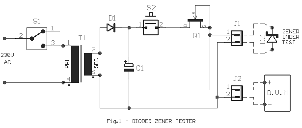
| Many times we have found itself in the necessity to use a
Zener diode and cannot to know the voltage of operation. Many times we cannot read the
characteristics or the type that is written on her. In
this case, but in different we can also use the circuit of Fig.1. The T1, D1 and C1 they
constitute a system of half-wave rectification. If
push the switch S2 a DC current passes in from current limiter Q1 and the diode Zener DZ
which we check. Q1 stabilizes the current in
the price of 10mA independent from the zener voltage that we have connected in the
connector J1. In the connector J2 we connect
a digital voltmeter. There we see the voltage
in the zener DZ. The circuit is reliable for
measurements down to 25Volts. You have clue of low voltage 0.8Volts likely the diode DZ,
is connected reverse. Change the polarity of
diode DZ. Pop_Elect80
|
|||||||||||||||
|
|||||||||||||||
|
