Stereo
Power Amplifier 4W-8W with TDA2005 |
|

|
Fig.1 |
�� ������� ���
�������� ��� Fig.1,
����� ���� ������������� ��������� ������
�������� �� Class AB ���
������ ���������� ��������� ��� ������������ �� TDA2005. ����� ������ ��
������������� ��� ���� �������� ���������
����������. �� IC1 ���� ���������
��������������� ���� ������� ��� ��� �������
���������. ���� �����
�������, ��� ������� ���� ������ ���. � ����
����������� ������ �� �������� ��� +9V ��� +18V �� �������� �������� 1 ��� 2
Amps. � ������� ����� ������ ��
������ �� ��� ������ ���������� ��������
����������� 2� ��� ���� ����������� +15V, �� ����� ������� 2� � 2
�������� ��� 4� ���������. ��������� ������� 4W/ch ������ �� ������ �� ����
+15V, �� ����� 1A �� ������ 4�. �� C4-5
����� �������� �������� ���� ��������, ���
��������� �������� ������, �� C7-11 ��� ����� �� ��������
�������� ���� �������, �� C8-12 ���������� �� �������
����� ��� ������� ���
������� ��������� ��� ���������� ��������. �� ����������� R2-3 ��� R4-5 ���������� ��
������� ��� ���������. �� ���������� C9/R6 ��� C13/R7 ������� ���
������ ���� ������ ���������� ����������
����������� ���� �� �����. ��
�������� C1-2 ������ �������� ��� ����������� ���
����� ��� ������������. �� ������ ����� ��� �� 1+(R2/R3) =1+(R4/R5)=37, � 31dB, ����� �����������
���������� ���� ������ ��� �� RV1. �
������ ��� ���������� ��������� R3 ��� R5 ������ �� ������� ��
�������� ������. � ������� ���� ����������� ���
������� ����� +18V.
������ �� �������� ��� ���� ����������� ����
���� �������� ��� �������.
|
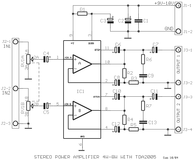
| This circuit [Fig.1] is a class AB stereo audio
power amplifier designed by Quasar for quality hi-fi applications using a TDA2005 module. It
is easy to construct and has a minimum of external components. The module has output
current protection and thermal protection. This is circuit, which produces an excellent
sound. The supply voltage required 9V-18V DC at 1 to 2 Amps. Maximum output power will only be obtained with a power
supply of at least 2A at 15V DC, and using 2 Ohm speakers or 2 by 4 Ohm speakers in
parallel. However approximately 4W/ch. can be obtained with only a 15V DC, 1A supply into
4ohm loads. The C4-5 are input coupling capacitors and block DC, as do
C9-13 which are the output coupling capacitors, and C8-12 which block DC from the feedback
loop to the differential inputs. R2-3 and R4-5 set the level of feedback. C9/R6 and C13/R7
provide a high frequency load for stability where loudspeaker inductive reactance may
become excessive. C1-2 provides power supply decoupling or filtering. The gain is equal to
1+(R2/R3)=1+(R4/R5)=37, or 31dB, minus any input attenuation. Reducing the feedback
resistors R3 and R5 may increase the gain. The maximum supply voltage circuit is 18V. Check the power
supply voltage and polarity before connecting to the circuit. |
|
|
Part
List |
|
| R1=120Kohm 1/2W 5% |
C1-9-13=100nF 100V MKT |
C7-11=2200uF 16V |
| R2-4=1.2Kohm 1/4W 5% |
C2=220uF 25V |
C8-12=220uF 25V |
| R3-5=33 ohm 1/4W 5% |
C3=10uF 25V |
IC1=TDA2005 |
| R6-7=1 ohm 1/2W 5% |
C4-5=2.2uF 25V |
J1=2 Pole Terminal Block |
| RV1=2X10Kohm Log. Pot. |
C6-10=100uF 25V |
J2-3=3 Pole Terminal Block |
|
|
|
Specifications |
|
|
Power Supply |
9�18V at 1�2 A |
|
|
Power output |
>8 W RMS/ch. at 2ohm 16V DC
supply. |
|
|
>6W RMS/ch.at 4ohm 16V DC
supply |
|
|
>4W RMS/ch.at 4ohm 12V DC
supply |
|
|
THD |
<0.1% @ 1W, 4ohm |
|
| 0.018% at 1W
RMS @ 4 ohm and +15V supply |
| Frequency
response |
~15 Hz to 50
kHz, �3 dB |
|
S/N ratio |
>80 dBA. |
|
|
Input level |
~160 mV for full output |
|
|
Gain |
~31 dB maximum. |
|
|
|
Sam
Electronic Circuits 9/04 |
|
|
