Audio Preamplifier with Digital Volume |

|
�� �������
����� ���� ������������ �� ������� ������� ���
������� ��� ����. ����� ���������� �� ����
������� �� ������� ������. ��� ����� ������ (Fig.1)
��������� �� ������� ������� ��� ������������
�������������. � ������� ������� ��� ���
���������� ���������. ��� S1 (UP), ��� �������� ���
������ ��� ���� ��� ��� S2 (DOWN), �������� , ���
��������� ��� ������, ���������� ���� ���
���������� IC1A-B ,��������� ���� ��������
����������� R-S (IC1C-D ), �� ���� ������� �����������
� ���������� ��� ���������� IC3. � ���� IC2B
����������� ��� �������������� ��� ����������
��� ���� ��� �������� ��������. �� ��� S4 ������
��� ���������� �� ���������� �� ������� ��� ����
��� ����� �� ��������� ���� ��� RESET � ���� �������
���� ��� �������. ���� � ���������� ����� ����
������� ���� ���������� �������� ������ ����,
���� �� ��� �������� S3 ������ ��� ���������� ��
���� �� ��������� MUTE, �� ���� ��������� ��� ����.
�� ������ �� ��������� ��� ���������� ���
���������� � ����� ����� ���������� �
8V. �� ������� �����������, ��� ��� ������� A,B,C,D,
���������� ���� ����������� �������� ��� IC2-3 ���
Fig.2, ��� �� ������ E,F,G, ���������� ����
����������� ������� ��� ������������ (Fig.3).
The circuit is a
preamplifier with digital regulation intensity of sound. He is separated in three
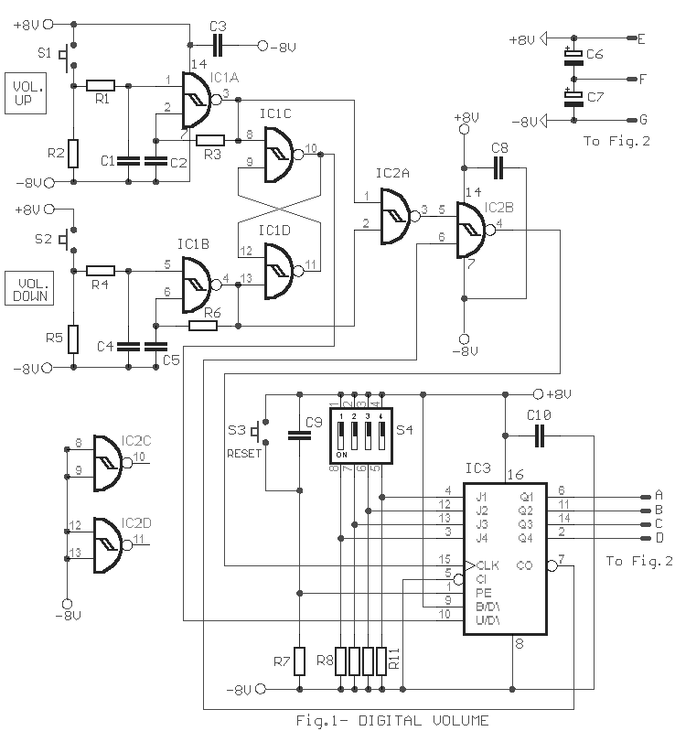
departments. In first schematic (Fig.1), is found the circuit of control
of electronic potesometer. The control become from two pressing switches. The S1 (UP),
that put up the intensity of sound and the S2 (DOWN), on the contrary, that lower the
intensity, checking them two oscillator follow a bistable multivibrator R-S (ICIC-D), with
that determined the direction of counter IC3.. The gate IC2B ensure deactivate the
counter in the limits of region of regulation. With the S4 we have the possibility
selecting the level of sound, in which it will come back after RESET or when we give
supply in the circuit. This operation is very useful when we select null level of sound,
then with switch S3 we have the possibility of going to situation MUTE, to rapid nihilism
of sound. It will be supposed you are careful the supply of circuit, which is symmetrical
� 8V. The logic conditions, from outputs A,B,C,D drived on correspondingly
inputs IC2-3 in Fig.2, the points E,F,G linked on correspondingly outputs from power
supply (Fig.3).
|
| R1-4-7=100Kohms |
C1-3-4-5-8-9-10=100nF |
IC3=4029 |
| R2-5=10Kohms |
C6-7=10uF 25V |
S1-2-3=Push button switch
[n.o] |
| R3-6-8-9-10-11=1Mohms |
IC1-2=4093 |
S4=DIP switch |
|

|
��� �������
������ (Fig.2), ������� � ������� ���
����������� ��� �������� �� ������ �����
������������ ���� 16 �������� ���� ����������
����������. ��� �� ����������� ����� ��� �� IC2-3
,���� ��� ���� ������. ��� ������� �������� ���
��� ����� ��������� ������������. ��� ��� ������
IC1A-B ��� ��� ���� ����� IC4A-B ,��� ����� ��� ���
������ ��������. � �������� ��� IC4A-B ������ ��
������� ������� �� ��� ����� ��� �������,
���������� ��� ���� ��� R38-40 . ��� �����������
���� ������ ���� �������� ��������, ���� ��
������� ������� �������� ����� ������� ���� ��
������ ��� ����� �������� �����������,
����������� ��� �� ���������� ��� ����� ��
�������� �������� �����������.
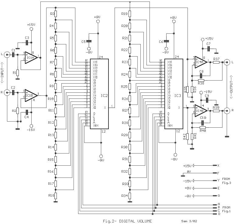
In second schematic (Fig.2), become the choice of resistors of divider,
what is connected in the 16 entries of one analog multiplexer. Here the multiplexers they
are two IC2-3, one for each channel. In the circuit they exist also two dual analog
opamp.. One, in the input IC1A-B and one, in output IC4A-B, that make also a light gain.
The gain of IC4A-B can change depending on our own needs, changing the value of R38-40. If
we add in the input a rotary switch, so that we make choice of various sources of input,
then we will have a complete qualitative preamplifier, exempted from the problems that
have classic mechanic potesometer.
|
| R1-2=47Kohms (All
Resistors 1/4W) |
R37-39=100ohms |
C8-10=100pF mylar or ceramic |
| R3.......R34=Tolerance 1-2%-See
Table1 |
R38-40=2.2Kohms (See Text) |
IC1=TL072 |
| R35-42=100Kohms |
C1-2=10uF 63V MKT |
IC2-3=4067
(MUX) |
| R36-41=1Kohms |
C3-4-5-6-7-9=100nF 100V MKT |
IC4=NE5532 |
|
|
Table 1 |
Resistors |
Step |
Channel L |
Channel R |
~2.5dB |
~3dB |
| R3 |
R19 |
4K7 |
3K8 |
| R4 |
R20 |
3K3 |
2K7 |
| R5 |
R21 |
2K7 |
1K8 |
| R6 |
R22 |
1K8 |
1K2 |
| R7 |
R23 |
1K5 |
1K |
| R8 |
R24 |
1K2 |
680R |
| R9 |
R25 |
820R |
470R |
| R10 |
R26 |
680R |
330R |
| R11 |
R27 |
470R |
220R |
| R12 |
R28 |
330R |
150R |
| R13 |
R29 |
270R |
120R |
| R14 |
R30 |
180R |
82R |
| R15 |
R31 |
150R |
56R |
| R16 |
R32 |
120R |
39R |
| R17 |
R33 |
82R |
27R |
| R18 |
R34 |
220R |
68R |
| Total |
18K5 |
12K7 |
|
|
|
��� �����
������ (Fig.3), ������� ��� �������� �����������, ��
������������� ��� ����������� ��� �� ���������
��� �� ������� �����.
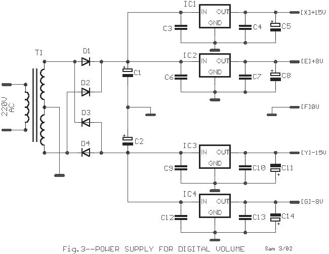
I n third schematic (Fig.3), he exist classic power supply, with
separated the supply�s for the analog and digital department.
|
Part
List For Power Supply |
|
|
| T1= 2X15Vac-30VA |
C3-4-6-7-9-10-12-13=100nF
100V |
IC2=7808T |
| D1....4=1N4002 |
C5-8-11-14=47uF 25V |
IC3=7915T |
| C1-2=4700uF 40V |
IC1=7815T |
IC4=7908T |
|
Sam
Electronic Circuits 3/02 |
|
|


