��� ������
����� ��������� �������� ����� �� ��� ����������
������, ������������ ��� ������� ��� �� ���� ���
���������� �� ������� ��� ������ ��� �� ��������
���� �������� �� ���������. ���� � ���������� ���
��� ����� �� �������. �� ������� ���������
��������� �� �� ��� ������� ��� �����������
�������. � ������ ��������� D1��� D4, �����������
��� ����������� �� ������� ��� ����� ����������
��������. ���� ������ �������� ��� �����
��������, ���� � ���� ���� ���������� ����� 50V ���
70V �������. H ���� ���� ���� ��� ������� ��� ���
����������� R1-2 ��������� ��� ���� ��� Fet Q1, ����
���� �� ��� ����. ����� ������� ��� �������� ����
� ���� ���� ������ ������, �� Q1 ���� ��� �� D6
�������, ���������� ��� ��������� ��� �������.
���� ��� Q1��� ��� R3 �� ����� ��� �������� �� Led D6
�� ������������ ��� 10mA. � ������ zener D5 ���������
��� ���� ��� ����� ��� Q1 �� ������� ����� ��� 10V,
��� � �������� C1 ���������� ��� ������ ���
������������ �������. ��� �������� ����������
����������� ��� ����������� ��� ����������
������ �� �������������� � R1 �� ���� �����������
����� (��� 220�). �� ���� ������ ��� ��� ��� R3, �
����� ������ �� ����������, ��� �� �������
��������� ��� ����� ��� R3. �� ������� ����������
�� ���������� +3V ��� +9V, ��� ��������, ���� ��� �
���������� ����� ������ �����.
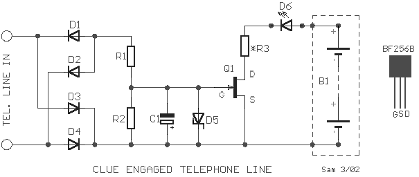
If we have a lot of
parallel telephones on a telephone line, we needed a unit that will have the possibility
of showing if somebody of the telephone has raised the earphone. Our this possibility give
the circuit. The circuit is connected at parallel with the two cables of telephone line.
The bridge of rectification D1- D4, protect and ensure the circuit from error polarity
connection. If no telephone is not raised, then voltage in telephone is 50V until 70V
roughly. This voltage via the bridge and resistors R1-2 turn on the gate of Fet Q1, in
order that this not open. As soon as is raised a telephone then the voltage in line fall,
Q1 turn on and the D6 it lighten, showing the situation of line. Because of the Q1 and R3
the current that leak Led D6 it is limited in 10mA. The diode zener D5 prevent the voltage
of gate of Q1, to pass above 10V, while capacitor C1 function as filter for parasitic
pulses. If they exist problems of adaptation and operation of circuit should is replaced
the R1 with other of bigger price (until 220K). The himself is also in effect for R3, who
can be suppressed, if the circuit work and without the R3. The circuit function with
supply + 3V until + 9V, from battery, one and the consumption is enough small.
|
