���� ��
������� ��� ����� ��� ������� ���� ������� ����
������ ���� - ���� , ���� �� LED ������� ���������
�� ��� ���� �� ���� . ����� ������ ���� ��� � ����
���� ���� ����� ���� ��� �������� ������ ���� ��
����. ��� clock ���������������� ��� �����������
IC3A-B , � ������ IC3C ����� ���� ���� buffer. �� R1, TR1,C1,
���������� ��� ���������, ��� ��� ��� ��������
��� ������� . �������� �� ������������ ��� TR1 ���
�� ��������� ��� ������ ��� ��������� � ��
��������� ��� ���� ��� C1, �������� ��� ��������
��� ������� �� ���������. �� ���� ��� Clock �������
��� �� IC1C-D, ���� �������� ����������� �
����������� ����������� (synchronous up/down counter), ��� IC2.
� ���������� � ����������� ����������
���������� ��� ��� ����� ICA-B, ��� ���������� ����
���� �� ����������� ��� set/reset flip-flop. �� Flip-flop ����
������� ��������� , ���� ������� �� LED D1 ��� D10, ���
���������� ��� ���� ��� ������, ������������ ��
������� �� �������� ���� ��� ��������
����������. � ������ ����� ����������� , ���
����� �� ���� �� �������. �� �������� ������ ���
IC2, ������� ��� �������� ��� IC4, ��� ����� ����
���������������� BCD, 4 ������� �� 10. �� ������ ���
IC4, ���������� �� �� LED D1-10. ���� ��� ��� ��� 10
������� ��������� �� ��������� [H], ��� ���
��������� [L] ��������� ��� ��� ��� ���� ��� LED's,
���� ����. ���� ���� ��� ���� ���������� ������
��� IC4 ������� [L] ���� ������ ��� �� ���������� LED.
��� ���� ��� IC4 ������ ��� �������� ,��� �������
�� ������������ ��� �������� �� �������������: 1)
�� �� 7442 ��� ����� ��� 16mA, ���� ������� ��� ��� 2)
�� 7445 ��� ����� 80mA.
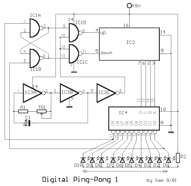
This circuit us gives the
sense of movement of ball up down, after the LED turn on successively the one afterwards
the other. As soon as it reaches in the one or in the other end it makes again the
opposite movement to behind. As clock are used two inverters IC3A-B, the third IC3C are
have role buffer. The R1, TR1, C1, determine the frequency, hence also the speeds of
movement. We can adjust the TR1 in order to we achieve the change of speed or we change
the price of C1, proportionally the speed that we want to achieve. The signal of clock
passes from the IC1C-D, in the entries increasing or decreased enumeration (synchronous
up/down counter), the IC2. The increasing or clipping enumeration is selected by the gates
ICA-B, that is connected so as to takes shape a set/reset flip-flop. The flip-flop this
changes situation, when they turn on LED D1 and D10, that is found in the limits of bar,
forcing the circuit to work to the opposite direction. This circle is continued, as long
as it is in supply the circuit. The four exits of IC2, drive the entries of IC4, that are
a decoder BCD, 4 lines in 10. The outputs of IC4, connect with LED D1-10.Every from the 10
exits remains in situation [H], while a situation [L] travels from a end of LED's, in the
other. When one from output pins of IC4 becomes [ L ] then turns on also the corresponding
LED. In the place of IC4 we have two choices, as long as report completed that we can
place: 1) with the 7442 us it gives until 16mA, in his exits and 2) the 7445 that it gives
80mA.
|
