Digital Volt and Ampere meter |
|
|
|
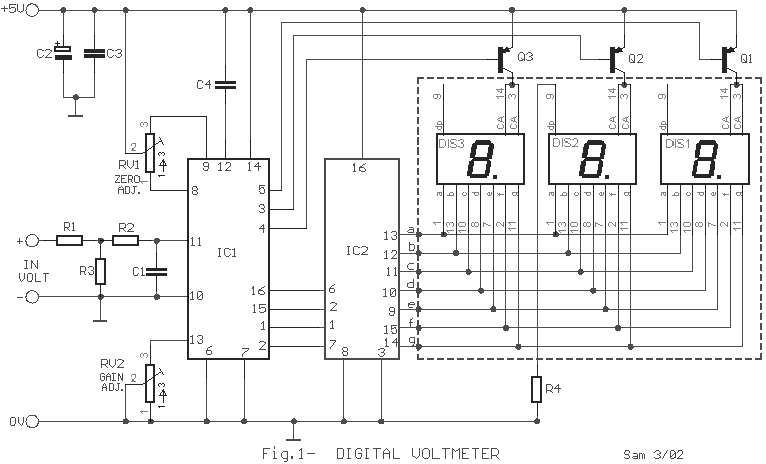
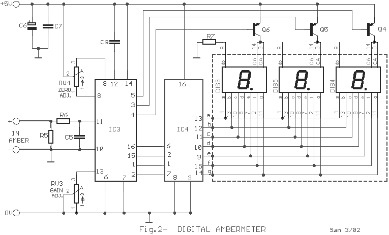
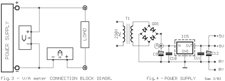
Even if the digital multimeters have dominated in a lot of applications, in the measurement, exist the need for existence of instruments of clue in various appliances, voltage and current, as in power supply or elsewhere. The circuits that give make this precisely the work, measure the voltage in terminal a circuit and the current that passes in his. The circuit does not present particular difficulties for somebody that has a small experience. The two circuits are the himself, with a small difference only in their input, when they have they measure voltage or current and in connection that concern decimal point [ dp ]. In the department of input IC1 and IC3, exist the CA3161E, that is a A/D Converter for 3-Digit Display. In the drive of Display IC2 and IC4, exist CA3161E, that is a BCD the Seven Segment Decoder/ Driver. As it appear in Fig.1, that concern the voltmeter in input [ + IN ], exist in series a what resistor R1 in combination with the R3 create a voltage divider. On the contrary in the Fig.2 that it concern the ampere meter, this resistor does not exist, because the circuit is connected differently, thus the current pass through the R5, creating a fall of voltage, in her terminal, proportional current that it pass from this. Adjustments Voltmeter: Short circuit in the input, pins 10 and 11 [IC1] and we regulate the RV1, until we take clue in the Display, zero in all the digits. We rectify and connect in the input a external voltage roughly 900mV. With the RV2, we regulate so that we take the clue 900mV in the Display. At the same time, we check this voltage with a external multimeter, of good quality and precision. Amperemeter: Short circuit in the input, pins 10 and 11 [IC3] and we regulate the RV4, until we take clue in the Display, zero in all the digits. We rectify and we connect in + IN point, provided that we place in series with the positive pole, of battery, a resistor 10R/10W and in the �IN, a new battery 9V. We regulate the RV3 so that we take clue in the Display 0.90A. We check simultaneously the correctness of measurement with a external digital ambermeter. A point that it should we are careful, the capacitors C4 and C9, it should they are very good quality. Also the various in the placement of resistors R4 and R7. of connection two circuits, for measurement voltage and current, appear in the Fig.3. The power supply that is public for two circuits appears in the Fig.4. If exist suitable constant supply in the appliance in which will be placed permanently the circuits, then can remove the T1 and bridge GR1 and is connected this voltage, in point A. The IC5 good is placed in heatsink. Feature V in maximum: 100V [99.9V] A in maximum: 10A [9.99A] Max. measurement Voltage Error: 100mV Max. measurement Ampere Error: 100mA
|
|
|


