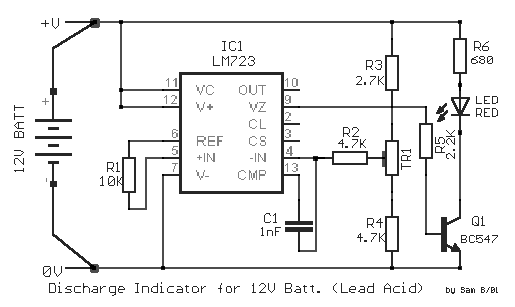
���� �������
����������� ��� ��������� �������� , ������� �
����� �� ������������. ���� �� ������� ����� ���
�������, ��� ���������� ����� ��� ���������� ,
�������������� ��� ��������� ��� ����������.
���� ��� ��������� � ������ ���� ��� ��������� 12V
��������, ��� ����������� �� ��������� ���� ���
10.8V, ���� ������ ������������� �� �� ������ ��� Led
, ���� � ���� ����� ���� ��� ���� ��� ����. ��� ��
��������� ��� ������ , ������������ ��� ����
������� ��� ��� ������� ��� �� ������ �� ���
��������� �� ��� ���������� ����. ��� ��� ���
����� ������������ ��� ����������� �� IC1- LM 723. �� ���������� �������
��� ���������� ���������� ����� ������ ���
���������. ��� IC1/6 ����������� ��� ���� �������
+7.15V, ���� � ���� ������� ����� ���������� ��� + 9.5V.
� ������� ���� ����������� ��� IC1/5. ��� IC1/4
����������� ��� ����� ��� ������ ������� ,���
��������� ��� �� ������� TR1. �� IC1 �����
���������������� ��� ��������� �����. ���� ����
� ���� ��� IC1/4 ����� ���������� ��� ��� ���� ���
IC1/5, ���� � ������ ��� IC1/9, ���� ������ ���� [L], �� Q1
����� �� ������� ��� �� LED ����� ������. ��� ��
������ �� LED ������ � ���� ��� IC1/4 �� �����
��������� ��� ��� ���� �������� ��� IC1/6, ����� �
������ ��� IC1/9 �� ����� ����� [H], �� Q1 ���� ��� �� LED
������. ��� ��� ������� ��� ���������� ��
����������� ��� ��������� ����������� , �� �����
���������� �� ���� ����� +10.8V, ��� �����������
���� ������ ��� ����������. ���������� ��
������� TR1, ���� ���� �� ������ �� LED ,�� ���
��������� �������� ��� ����� ��� ������������.
�� ���������� ������� ��� ����������, ������ ��
��������� ��������� ����� ������ ��� ��������� ,
������ �� �� �������������� ���� ��������������
��������� 12V (��������).
In perfect
discharge the batteries of lead acid, exists the fear they are destroyed. This circuit
makes the work, this detection of discharge, protecting the batteries from destruction. At
the discharge the polar voltage of batteries 12V of Lead acid, is not allowed it is
decreased under 10.8V, thus we have warning with the turn on of Led, when the voltage
falls under this price. In order to we achieve the control, we needed a stability voltage
and a circuit that could him compare with the checked voltage. And two these condition
provide to IC1- LM 723. The terminal entry of
circuit they are connected in the poles of battery. In the IC1/6 is presented a stability
voltage + 7.15V, when the voltage of entry is bigger than + 9.5V. The stability voltage is
applied in the IC1/5. In the IC1/4 is applied a part of voltage of entry, that is checked
by the trimmer TR1. The IC1 is as voltage comparator. Thus when the voltage in the IC1/4
is bigger than the voltage in the IC1/5, then the exit of IC1/9, has low level [ L ], the
Q1 is in cutting off and the LED it is off. In order to it turns on the LED should the
voltage in the IC1/4 become smaller than the voltage of reference in the IC1/6, whenever
the exit of IC1/9 will become high [ H ], Q1 conduct and the LED turn on. For the
regulation of circuit we will need exterior supply, which is regulated has expense +
10.8V, him applies in the entry of him circuit. We regulate the trimmer TR1, so as to it
turns on LED,me the least alleviation of voltage from supply. The terminal entry of
circuit, it should they are connected directly in the poles of battery, it can be used
where we use batteries 12V of (Lead acid). |
