Electronic Switch with Delay Time For Lambs |
|||||||||||||||||||||||||||||||||||||||||||||||||||||||||||||||||||||||||||||||||||||||||||||||||||||||||||||||||||||||||||||||||||||||||||||||||
| . | |||||||||||||||||||||||||||||||||||||||||||||||||||||||||||||||||||||||||||||||||||||||||||||||||||||||||||||||||||||||||||||||||||||||||||||||||
|
|||||||||||||||||||||||||||||||||||||||||||||||||||||||||||||||||||||||||||||||||||||||||||||||||||||||||||||||||||||||||||||||||||||||||||||||||
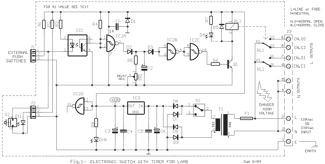
A circuit that will
find enough applications. Basically the designing became in order to exist delay in quench
one or more lamps in a stairwell or in any other space exists this need. It can become
use, for the control various motor or other appliances, what is connected in the contacts
of J3. The activation command is given by exterior pressing switches connected parallel
[Fig2]. Does not exist restriction in the number of these switches. The switches lead with
a simple cable of three cables with small diameter, to the J1. Each switch is constituted
by the pressing switch and Led that works constantly, facilitating to find the place of
switch in dark spaces. If the switches are placed in exterior spaces, it will be supposed
they are waterproof. Parallel to the J2 terminate the switch S2, Led D9, which can be
placed above in the box of circuit or near this or can be used if it does not need. If
pressing anyone of switch excited the Led of optocoupler IC1 the transistor closes and
grounding the entries of gate IC2A, his exit becomes High. Capacitor C3 charges via the D2
roughly in the supply voltage. The exit of IC2B becomes Low the exit of IC2C becomes High.
Transistor Q1 excites it and the RL1. His contacts close and it turns on the lamb that we
have connected in his contacts, and it remains thus until discharge the C2. As soon as we
stop pressing some switch the exit of IC2A goes Low, the C2 it begins discharge through
the R5 and the TR1. Proportionally the resistance of TR1 changes also the time of C2
discharge, hence also the time that the RL1 remains excited. This time depends from the
prices of C2, R5 and TR1. The use optocoupler facilitates in order to we avoid problems of
accidental excitation from parasitic signals in the entry of IC2A. |
|||||||||||||||||||||||||||||||||||||||||||||||||||||||||||||||||||||||||||||||||||||||||||||||||||||||||||||||||||||||||||||||||||||||||||||||||
| The circuit supplied
by one relatively simple power supply with stabilization in +12V dc. With switch S1 we cut
the supply of circuit if it needs. |
|||||||||||||||||||||||||||||||||||||||||||||||||||||||||||||||||||||||||||||||||||||||||||||||||||||||||||||||||||||||||||||||||||||||||||||||||
The D15 shows the circuit supplies with power and the D12 turns on when the RL1 is on. If him you do not need you can him suppress? The power of load that will supply the RL1 depends from his contacts. Can place relay with one or more contacts. |
|||||||||||||||||||||||||||||||||||||||||||||||||||||||||||||||||||||||||||||||||||||||||||||||||||||||||||||||||||||||||||||||||||||||||||||||||
| Attention,
in the entire region where it exists the high voltage of network, exists always the danger
of electrocution. |
|||||||||||||||||||||||||||||||||||||||||||||||||||||||||||||||||||||||||||||||||||||||||||||||||||||||||||||||||||||||||||||||||||||||||||||||||
|
|||||||||||||||||||||||||||||||||||||||||||||||||||||||||||||||||||||||||||||||||||||||||||||||||||||||||||||||||||||||||||||||||||||||||||||||||
Led connection of external switches. |
|||||||||||||||||||||||||||||||||||||||||||||||||||||||||||||||||||||||||||||||||||||||||||||||||||||||||||||||||||||||||||||||||||||||||||||||||
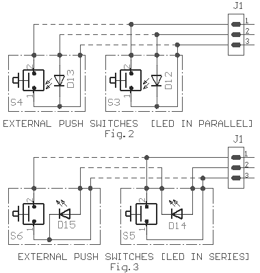
| In Fig.2-3 appear
two ways of connection of clue Led that are found on each external switch. In the Fig.2
the Led of all switches, are connected parallel the one with the other. In this case the
calculation of resistance R1 becomes as it appears in the Table1. The connection Led in
series appear in the Fig.3 and the calculation of R1 value exist in the Table2. If you do
not need Leds then you can abolition. |
|||||||||||||||||||||||||||||||||||||||||||||||||||||||||||||||||||||||||||||||||||||||||||||||||||||||||||||||||||||||||||||||||||||||||||||||||
|
|||||||||||||||||||||||||||||||||||||||||||||||||||||||||||||||||||||||||||||||||||||||||||||||||||||||||||||||||||||||||||||||||||||||||||||||||
Various connection modes, of external loads. |
|||||||||||||||||||||||||||||||||||||||||||||||||||||||||||||||||||||||||||||||||||||||||||||||||||||||||||||||||||||||||||||||||||||||||||||||||
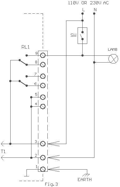
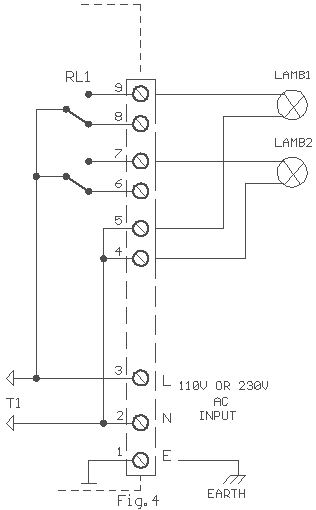
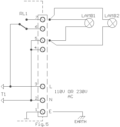
| Various connection modes exist in the Fig.3,4,5. In the Fig.3 exist one of typical house connection, where the Sw is the existing switch of wall house. When the Sw is closed lamb it turns on independent from the operation of circuit. If the switch Sw is open then the circuit takes on her operation. | |||||||||||||||||||||||||||||||||||||||||||||||||||||||||||||||||||||||||||||||||||||||||||||||||||||||||||||||||||||||||||||||||||||||||||||||||
| . | |||||||||||||||||||||||||||||||||||||||||||||||||||||||||||||||||||||||||||||||||||||||||||||||||||||||||||||||||||||||||||||||||||||||||||||||||
|
|||||||||||||||||||||||||||||||||||||||||||||||||||||||||||||||||||||||||||||||||||||||||||||||||||||||||||||||||||||||||||||||||||||||||||||||||
| . | |||||||||||||||||||||||||||||||||||||||||||||||||||||||||||||||||||||||||||||||||||||||||||||||||||||||||||||||||||||||||||||||||||||||||||||||||
|
|||||||||||||||||||||||||||||||||||||||||||||||||||||||||||||||||||||||||||||||||||||||||||||||||||||||||||||||||||||||||||||||||||||||||||||||||
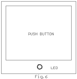
Example of placement of Led in exterior switch. |
|||||||||||||||||||||||||||||||||||||||||||||||||||||||||||||||||||||||||||||||||||||||||||||||||||||||||||||||||||||||||||||||||||||||||||||||||
|
|||||||||||||||||||||||||||||||||||||||||||||||||||||||||||||||||||||||||||||||||||||||||||||||||||||||||||||||||||||||||||||||||||||||||||||||||
