���� �� ������� ����� ��� ���������� , �������
�������. �������� ��� ������� 1�� ��� 1���. �� IC1
schmitt trigger ��� �������� �� ���� ������� ��� ��
���������� �� ������ ������� ��������� ��� ��
IC2-3-4. �� ��� ������ ����� ���� ������ ��� IC2/1,
��������� ���� ������ ''carry'' ��� IC3/5. ��� ����
������ �� IC2 �������� ��� ���������� ��� DIS1 ,
������� [0] , �� IC3 �������� �� DIS2, �� ������ [1]. ����
���� ������ ��� IC3 ������ ��� � ������� ������, ��
DIS2 ����������� [0] ��� �� DIS3 ����������� [1], (��
�������� ���������� 100, ������� �� display �� �����
�����). � ������ ''carry'' ��� IC4/5, ������ ��
�������������� ��� �� ������ �� �������� ������
(�����������) ��� DIS1, ��� �� ������ ��� ���������
���� ��� ����� ��������. � ��������� ������� ��
�� ��� ���� ��� ������ timer (IC5A). � ��������� S1
�������� ��� ������� ��������� ���� �� 1sec ���� ��
1ms. ���� ��� �������� ����� ��� �������� , ��
������� ���� ��� (IC5�), ������� ��� �������
����������� 2 � 3sec.,���� ��� �������� ��� ������
�� ����������� ������������� ��� ��� ������ ���
�� displays ������ �����. ��� ����� ��� �����������,
���� ������ RESET ������� ��� ������� ��������� /
�����������. �� ������� ������ ����� ���� ��� ��
Q1-IC1, �� ����� �� ������ �� ����������� ���
������� ��� ����� ��� jack ������� , ���� �������
����������� ������� ������ ����������. ��� ���
������� , �������� �� ���������������� ���
���������� ����� ��������� (��� ��� �����
����������� ���) ��� ��� ��������� �������.
������� ��� �������� S1,���� ���� ��, �����������
���� ������ ��� ������ ��������� ��� ����������
�� ������� TR2, ���� �� ������� ��� ����� �������, �
����� ������ �� ��������� �� ��� ��������
�����������. ��������������� ��� ������� ��� ���
�� ����� ��� ���, �� ��� ��������� ��� ������
����������. � ���������� ��� ���������� �������
�� ��� �������� 9V, ��� ��������������� ��� ������
� ��� ��������� ����������� ��� ����������� ��
������ ������� ��� ��� �������.
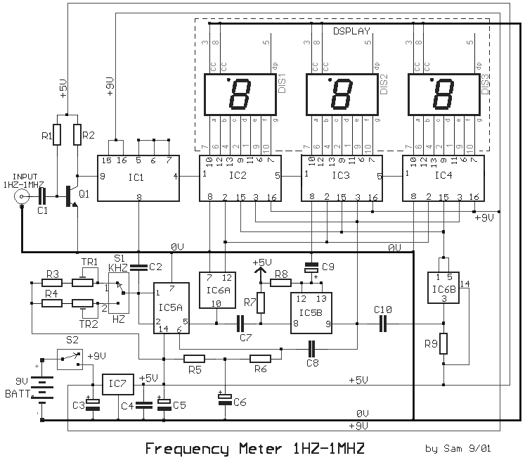
This circuit
is a frequency meter, low cost. It covers region 1HZ until 1MHZ. The IC1 schmitt trigger
that it regulates the signal of entry and him changes in reasonable level suitable for the
IC2-3-4. With the tenth pulse in the entry of IC2/1, is produced a pulse '' carry '' in
the IC3/5. The same moment the IC2 causes the depiction in the DIS1, show [0], the IC3
causes the DIS2, to show [ 1 ]. When in the entry of IC3 it reaches and the tenth pulse,
the DIS2 show [ 0 ] and the DIS3 show [ 1 ], (with total depiction 100, having the display
in right order). The exit '' carry'' off IC4/5, can be used in order to it turns on the
decimal point (comma) the DIS1, in order to it shows a situation over the limits of
measurement. The timed begins with the one of half double timer (IC5A). Switch S1 select
the interruption the time in 1sec or in 1ms. At the duration of this interruption, second
half the (IC5B), it produces a interruption of depiction 2 or 3sec., at the duration which
counter cut off by the entry and the displays remain OFF. In the end of depiction, a pulse
RESET, begins the interruption of time/depiction. The critical point is round the Q1-IC1,
which should be placed as long as it becomes more near in the jack of entry, to reject of
parasitic signals of high frequency. For the regulation, we can use a frequency meter good
precision (if you do not have you are lented) and a generator of signal. We put switch S1,
in place [HZ], we apply in the entry a low frequency and we regulate the trimmer TR2, so
that we take the right clue, which should suit with source frequency meter. We repeat also
the regulation for the department of KHZ, with a higher frequency. The supply of circuit
becomes with a battery +9V, if it is used as portable or from suitable power supply if it
is incorporated in some unit that exists already.
|
