Headphone Class A Amplifier [2] |
|||
|
|||
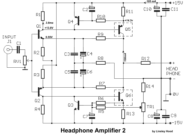
����� ��� ������� ��������� ���������� �� ������ ���� �, ����������� ���������, ����������� ��� ��� Linsley Hood �� 1984 ��� ������������ ��� ��������� Electronic Today International. ������ �� �������� ��������� ����� ��������� �������� ���������� ����������� ��� 50�, �� ������� ���� �� 600�. �� ���������� ������ ���������� �� ����� ������� 100mA, ���� ���������� � ����� ������� ��� ���������� ������ , ���� ��� � ����������� ��� ������������� ��� ��� ������ ��� �������� 100mA ����� ������ �����. � ���������� ����� ���������� 15V ��� ������ �� ����� ��� ��� ��������������� ����������� �� ��� ����� �������������� 7815/7915 � LM 317-337, ��� ��� ������ ��� �������� ������ ����������. �� �� RV1 ���������� ��� ������ ��� ������� ������� ��� �� �� TR1 ����������� ��� ���� offset ���� �����. ���� ��������� ��� �� ������� �������� , ��� ������� ��� ����� ��� ������ ��� �������� ��� �������� ��� ������. It is a very useful thing , to have a small headphone amplifier , capable of driving a couple of pairs phones. Fortunately, the headphone amp has a much easier job to do, in that neither the output power requirements nor the load characteristics are so severe, since headphones typically have a load, impedance , higher of 50 ohm, (typical 600 ohm), and only require 1-2V RMS. max, for normal output. Since only a low power output is required, a Class A stage, is perfectly feasible. For adequate Class A operation the output transistors Q5-6, should pass say 100mA each. With �15V supply this would mean 1.5Watts dissipation, so a smallish Heatsink, will be needed for each. With RV1 adjust input audio signal and Tr1 adjust the output DC Offset voltage for 0V (�30mV). For stereo application , you need two unit, of this amp. by L. Hood
|
| R1-4= 1.2Kohm | R14=68Kohm | C9-11= 100nF 100V ceramic |
| R2-3= 3.9Kohm | RV1= 10Kohm Log. pot. | Q1-3= BC184 |
| R5-10= 10Kohm | TR1= 10Kohm Trimmer | Q2-4= BC214 |
| R6=100Kohm | C1= 4.7uF 63V MKT | Q5= BD136 or BD538 |
| R7-9= 2.2Kohm | C2-7= 100uF 25V | Q6= BD135 or BD537 |
| R8= 150 ohm | C3-5= 100nF 100V MKT | |
| R11-13= 6R8 ohm | C4-6= 100uF 16V | |
| R12= 4.7 ohm | C8-10= 470uF 25V | All resistors is 1/4W 1% |
Sam Electronic Circuits 8/01 |
[ Home ] [ My Database ] [My Guestbook ] |
