��
������� ����� ���� ������ ���������-����������
������������ , ��� ������������ ��� ��� ������
��� ������������. � ������� ��� ������������
������� ��� �� ��������� ��1, �� ����� �����
��������� ����������. � ��������� ���
������������ ������� ��� 10�� �� ����������� 25� C
��� ������� ��� 1�� ����� 94� C. �� ������� TR1
�������� ��� ������ ����������� ���� ����� �� Q1-2,
����������� ��� Darlington, ����� , �������� ��� ����
�1 �� ������� ��� �� �� , �� ������. �� alarm
�������������� ���� � ����������� �����
���������� ��� ��� ��������������. �� ���������
������ �� ����� ������������ ������ ��� ��
�������� �������, ���� ���� �� ��� ���������� ���
��� �����������. � ���������� ��� ����������
������� ��� �������� 9V, ���� ��� �����
������������ �� ������� ���� , ���� �������� ��
�� �������������� �� ���� ��� ��� �������
�����������. ���� ������ ��� ���� �������� ��
���������� ����� ������ �������, ���� ��� �����,
��� ���� ������� �.�. ������ ������ �� ���������
��� LED,��� ������� �� ������ ��� ������ �������
��� ���������. � ������� ������� ���������� ��
��������� ��1, ���� �� ���� ��� ������ ������� ���
����������� (�� ������ ������ �� ����� ����
��������� ���� �� ��� ������ ������������) ���
����������� �� �������, ��� ���� ��������� ��
�������. �� ������� ��� ��������� �� ������� ��
�� ��1, ������ �� ����� �����������.
The
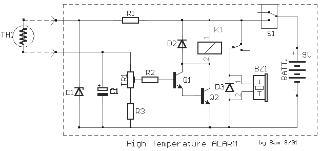
circuit is small regulatorof temperature, us warns for the increase of temperature. The
control of temperature becomes from the thermistor TH1, that is negative factor. His
resistance is altered between in the 10K in temperature 25� C and roughly in the 1K in
their 94� C. The trimmer TR1 regulates the precise temperature in which the Q1-2,
connected as darlington, conduct, making him relay K1 close also the buzzer BZ, sound. The
alarm is activated when the temperature becomes bigger than predetermining. The thermistor
it should he is placed far from the remainder circuit, in order that this is not in danger
from the temperature. The supply of circuit becomes from battery 9V, but if he is placed
in constant place, then we can him supply with one power supply . In the contacts of relay
we can connect what load we want, as a lamb, other circuit k.a. Also can is added a LED,
if we want to have also optical clue of excitation. The regulation becomes sinking him
thermistor TH1, in water which we know the temperature of (the contacts should are well
insulate so that do not have short-circuit) and regulating him trimmer, until excited the
circuit. The cable that we connect the circuit with the TH1, should be plate.
|
