��� Fig.1,
������� ��� ������� ��������� ��������� ��� ���
DC ����, ���� �������� [RL1], ���� � ���� ������ ����
��� ��� ������, �� ����� �� ����������� �� ���
������� D1-2 ��� �� RV1. �� ������������ �����
���������������� ��� ���� ��������� �����, ��
��� ���� �������� �� ����������� ����� ����
��������� 2 ��� � ���� ������� ���� �����������
���� ��������� 3. �� RL1 �������� �� ��������� ��
���� � ���� ���� ��������� 3 ������� ��� ���� ���
��������� 2. �� ������� ������ �� �������� ��
������ ���� ��� 5V, ���� ��� ��������� ������� ���
���������� R1. ��� Fig.2, ������� ��� �������
�������� ��������� ��� ������ �� �������� ��
����������� �������������� ���� ����� ���
������� 10mV. � ���� ������� ������ �� ��������
����� �� ��� ��������� 2, ��� �� ������ �������
���������� ���� ������� ������ 10mV ��� 3V. ���
������ ���� ��� 3V ������ �� ����������� ���
��������� �� ����� �� ��� ������ ��� �� ��������
��� ���� ���� ��������� 2, ��� ��������� �������.
�� ������� ������ �� ���������� �� �������� ���
����������� �� ���� ��������� ��� ��������, ���
����������� ��� ������� ��� ��������� 2 �� �����
��� ��������� 3 ��� ������������� IC2. �� �������
������ �� �������������� ��� ���������
�������������� ����� ���� ������ ���, ����� ��
��������� ����� � ������������� ����.
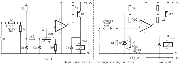
In Fig.1 A precision DC
under�voltage relay switch. The opamp is wind as a voltage comparator, with a reference
voltage applied to pin 2 and the test voltage applied to pin 3: the relay turns on when
the pin 3 voltage exceeds that of pin 2. The circuit can be made to trip at any voltage in
excess of 5 volts by suitable choice of R1 value. In Fig. 2 An over-voltage switch that
can be used to trip at any pre-set voltage in excess of about 10 mV. The input voltage can
be connected directly to pin 2 if trip values in the range 10mV to 3Volts are required.
For voltages in excess of 3 Volts, a suitable range resistor must be connected in the
position shown, to keep the pin 2 Voltage drive to suitable level. The circuit can be
converted to an under�voltage switch by transposing the pin 2 and pin 3 connections of
the op-amp. The circuit can be used as an AC voltage switch by first rectifying the AC
input signal.
|
