�� CD ����
����� ����������� ��� ��� ����������� ��������.
�������� ���� ������ ��� ��������� �� �����
������� ����� �� ������ ������� �������, �����
���� �������� ��� ��� �������� ������ PHONO, ����
�������� �������� �������. �� �������� C1-10 ������
�� ���������� ���� ���� �� ���������� �� ��
�������������� ��� ������� ��� ��������������
[1].�� ������� ����������� �� �������� ��� ������
���� ��� ������� �� ������ ������� ���
���������� �� ����� ��� ���������� �������� ���
��������� ������� �� �� ������� RIAA [Fig.2]. ���
�������� ���� ��� ������ ��� ��� ���������� ���
50�� ��� 500�� �� ������ ���� �������� ��� IC1-3,
������������ ��� ��� R4-5, C2 [R17-18, C11] ��� ���
��������� 2122�� �� �� �������� ������ R7-8, C3 [R20,21,
C12]. �� �������� C2,3,11,12 ������ �� ����� �������� 1% �
��� ��������� ��� ����������� �� ���
������������� ������� �� ����� ������ 5% [2]. ��
������� ������������ ��� ���� ���� ����
�����������, ����� �� ���������� ��� �� ��������
�������, ��� ���������, �� ��� ������� ���������,
���� �� ���������� ���� ��������. ��� �� �������
������ �� ����������� ���� �� ��� ����� ����� ,
��� �� ����� �� �������� ����� �� ������� RCA, ��
������� �����������, ��� ���� ����� ��� �������
��� � ������ Led D1, ��� ������ �����. ���� ����� ��
����������� ��� �������� ��� ���� ����� ������
���������. �� ���� ��� ��� ������� ���
����������, �� ��� ���� ����������� �������,
��������� �� ��� �������� ������ ������� ���
�������� � ��� �����������. ��� � ������ ���
������� ������ ��� ����� ���� ��� �������,
�������� �� ��������� ��� ����������� R9-22, ��
���� ���� ���� �� ������������� ��� ������.

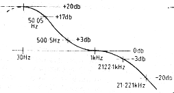
Fig.2- RIAA recommended equalization
characteristic
The CD henceforth has
prevailed for the reproduction of music. Exist however many that they dispose a old
classic turntable, with moving magnet head, they have however amplifier that does not
dispose a PHONO input, but dispose LINE inputs. The capacitors C1-10 should be selected
so, as to they suit with the head characteristics, that we use [1]. The circuit it
undertakes it simultaneously elevate the head low voltage in LINE level and it makes the
essential response correction according to the RIAA standard [Fig2]. This correction him
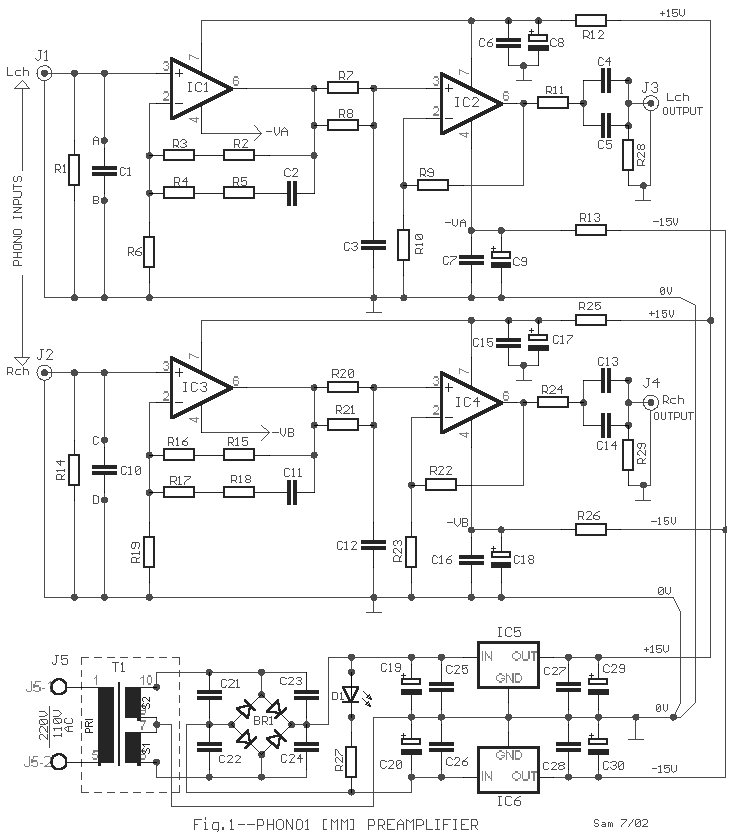
they make for the frequencies of 50HZ and 500HZ the filter in the feedback of IC1-3,
constituted from the R4-5, C2 [ R17-18, C11 ] and frequency 2122HZ with pathetic filter
R7-8, C3 [ R20,21, C12 ]. Capacitors C2,3,11,12 should have tolerance 1% or if they are
also measured matching with a capacitance meter, it can they are tolerance 5% [2]. The
circuit use one simple, but good power supply, is enough it�s armor-clad by the
remainder circuit, if it needs, with a aluminium, so that we avoid the noises. All the
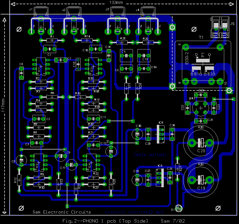
circuit can be placed in a small box, from which will only come out the RCA jack, the main
power cable, in the back box part and the Diode Led D1, in front part. Good it�s are
placed a Fuse and a good small switch. The signal from the circuit outputs, with a good
cable, is led to a free LINE input of amplifier or preamplifier. If the output signal
level, is not that we want, we can change the resistors R9-22, with other value so that we
adapt the level. |


