Power Amplifier 45W with HEXFET |

|
A ideal
solution for the make a good, low cost power amplifier. It�s a ideal solution for the
creation a system of home cinema. The preamplifier and the driver support in a operational
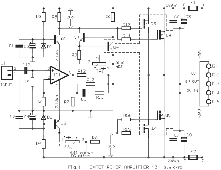
amplifier [IC1]. The voltage fall in resistors R5 and TR2/R6, drive the output FET's gates
and is proportional with the input signal level. Transistors Q1-2 function as voltage
stabilizers in the supply lines, but ensure also the essential voltage fall, because the
IC1 it should not they are supplied with voltage bigger � 18V.
The consumption of all types that can be used in the place of IC1, are 2 mA, this it means
voltage fall in terminal the R5 and TR2/R6 equal with the 2.4 until 2.6Volts. The current
regulation it become from transistors Q3-4 in Wilson connection and the current adjustment
of bias it becomes from the multiturn TR1 trimmer. The existence of trimmer TR2 in line with the R5
helps in the voltage minimization of DC offset in the amplifier output and the initially
value is regulated front works the amplifier so the total resistance of TR2 and R6 is
equal with the R5. TR2 can be suppressed provided that does not exist big difference in
the minimization the DC offset and be replaced the R6 value with the R5 value. The
Q5�.8, is in Drain follower connection, in provision Push-Pull, acquiring the
possibility of drive up to supply voltage, with result the refund is until 75%. For
thermic stability of amplifier essential is we place the Q4 near in the Q5-6 and above in
the heatsink as there is the essential thermic feedback, ensuring thus the bias stability.
This happens because for small current, the thermic factor in the FET is positive Thus with
increase of temperature in the Q5-6 is caused corresponding temperature increase in the
Q4. Then the Vbe of Q4 is decreased, thus the current source ��pull �' less current
through the R5, so that is decreased the Vgs the Q5-6. Thus the bias current comes back in
his initial value and remains certain. In the bigger operation current of amplifier the
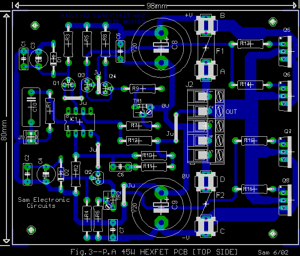
thermic factor of FET, is negative. Above in amplifier PCB and near in the output stage,
are found the capacitors C8-9 that they help in the benefit of current in short transient.
The bias current is regulated so that it�s roughly 200mA and her regulation it becomes
as follows: 1 ] In the place of each Fuse F1-2, we place resistor 10 ohms 1W. 2] Supply
the amplifier. If the resistors not burned or overheating, then regulating him TR1 so that
we take voltage fall, across the resistors equal with 2V. We leave the amplifier to work
for half hour roughly. We again measure the voltage fall and if it needs we regulate again
the TR1. If all go well then we remove the resistors and we place Fuses F1-2. 3 ] We adjust
TR2 so that we take in the amplifier exit [ J2-2 ], without input signal, DC voltage � 30mV (as smaller, so much better). In the place of IC1 they can is
placed one of their LF411, LF351, AD711 opamp.
|
| R1=47Kohm |
C1-2-6-7=100nF 100V MKT |
Q5-6=IRF9540 |
| R2-12=1Kohm |
C3-4=22uF 25V |
Q7-8=IRF540 |
| R3-4=3.3Kohm |
C5=220pF styroflex |
TR1=5Kohm trimmer multiturn |
| R5=1.2Kohm |
C8-9=4700uF 63V |
TR2=1Kohm trimmer multiturn |
| R6=[1.2Kohm] 820ohm
*See text |
C10=1uF 100V MKT |
F1-2=fuse 3A |
| R7=270ohm |
D1-2=15V 0.5W zener |
J1=2pin connector 2.54mm step |
| R8=220ohm |
IC1=LF411orAD711or LF351 |
J2=5pin connector 5mm step |
| R9=27Kohm |
Q1=BC550C |
|
| R10-11=22Kohm |
Q2=BC560C |
All Resistors 1/4W 1% metal film |
| R13-14-15-16=150ohm |
Q3-4=BC547B |
|
|

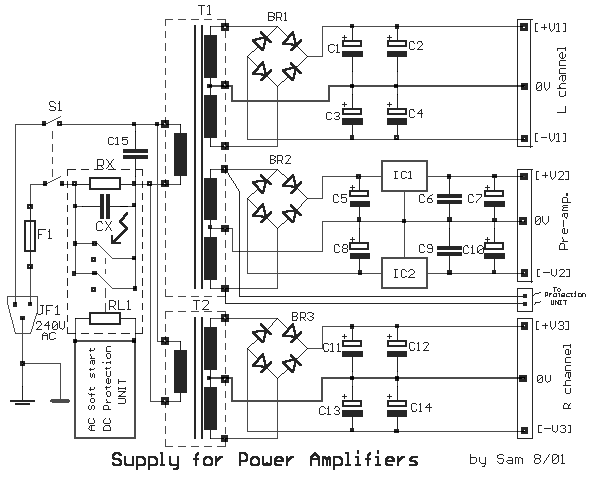
Fig.2--POWER SUPPLY |
The power
supply circuit, is a classic circuit. Proposed
power supply for amplifier 45W HEXFET is what appears in the above form. It has separated
supply for the various supply stages, for power output stage, for control stage, for
preamplifier supply and for protection stage. Whoever wants it can suppress department or
add a power supply for each channel, separating completely the channels between them. For
whoever it does not use the preamplifier circuit and protection can suppress proportional
coil. In his input exist the
soft starting circuit, that combine with the delay circuit and protection loudspeakers
from DC.
|
Supply Output Voltages |
|
|
+V1=+32V |
-V1=-32V |
|
|
+V2=+12V |
-V2=-12V |
|
|
+V3=+32V |
-V3=-32V |
|
|
| T1=2X22Vac 3A //2X15Vac 0.5A |
C5-8=1000uF 25V |
IC2=7912 Regulator
|
| T2=2X22Vac 3A |
C6-9=100nF 100V MKT |
F1=FUSE 2A slow block |
| BR1-3=400V 35A Bridge Rectifier |
C7-10=10uF 25V |
S1=2X2 switch 10A |
| BR2=4 X 1N4002 |
C15=33nF 630V Class X2 |
JF1=3 pole male plug |
| C1...4-11...14=10000uF 63V |
IC1=7812
Regulator |
|
|
|
SPECIFICATION |
| Power [rms] |
45W
in 8 ohm |
| 75W
in 4 ohm |
| T.H.D |
0.2%
in 40W |
| Frequency
Response |
5-20KHZ
�1dB |
| Input
Impedanse |
47K |
|
|
|
Sam
Electronic Circuits 6/02 |
|
|


