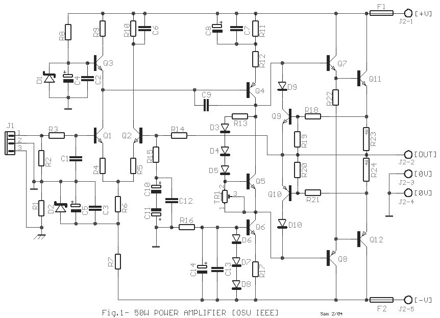
This
simple audio power amplifier was originally designed for a circuit board workshop,
conducted by the OSU IEEE Student Group. At the workshop, 20 participants each constructed
this amplifier, by etching and drilling the single sided circuit board, soldering all
components, and attaching a pre-built heatsink assembly with the output transistors. Three
workshops were held between 1995 to 1996. Though the design is simple, these amplifiers
have impressive performance, with a frequency response to approx 40 kHz, very low noise,
reasonably fast slew rate, and approx 50 watts (true "RMS" power) with the
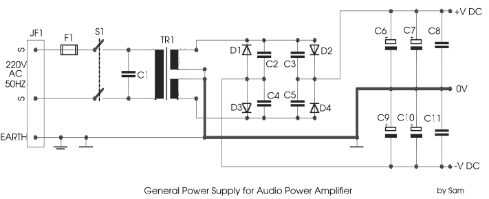
proper +/- 40 volt unregulated power supply.
Note:
The TIP33C and TIP34C have been discontinued and are generally not available anywhere. I
replace the Q11=TIP33C and Q12=TIP34C with BD249C and BD250C
Testing
If
any of these tests fail, the amp is not constructed properly... the easiest and best way
to find the problem is visual inspection.
- Turn
variable resistor fully counter clockwise (max resistance)
- Connect
to +/- 24 volt supply with 200mA current limit. No input and no output connected. Monitor
current from power supply with a current meter.
- Apply
power... if current is above about 25 mA, shut off immediately!
- Measure
voltage across the 1k resistor connected to the input stage and Vcc. The DC voltage should
be about 2 volt, or 2 mA of current through this resistor. Eg, if +V is at 24 volts, the
side of this resistor connected to the BC550C
transistor ought to be at about 22 volts.
- Measure
the DC voltage on the output line. It should be appox zero volts. +/-0.05 volts is
probably fine.
- Turn
the variable resistor slowly until the amplifier�s current consumption is approx 50 mA.
Turn slowly and be careful... if you turn too far you could damage the output transistors.
- Connect
an oscilloscope to the output and apply a low amplitude 20 kHz square wave to the input.
DO NOT connect any speakers during this test. This test should be done without the
C1=330pF capacitor installed. The amp should output a 20 kHz square wave with very little
"ringing". It should not oscillate.
- Solder
the C1 capacitor into the circuit.
- Shut
off the power, connect audio input and a speaker. Make sure the volume is turned all the
way down. Apply power... watch current meter again and shut off the power immediately if
the current jumps to something much higher than 50 mA.
- .Slowly
turn up the volume and see if the amp works. DO NOT turn it up very much... the amplifier
should not be operated with a supply less than +/- 30 volts. It should never be used for
high volume output without a power supply rated for at least 2 amps of current (8 ohm
load). After this initial test with +/- 24V at 200 mA (current limited) only a proper
power supply should be used which can provide enough current.
Source:[PJRC] |

