Audio Line High-End Preamplifier with ICs |
| Generally. |
| Afterwards
the Modular preamplifier presentation good is I present also a simpler circuit in the
manufacture but very good quality. And in this circuit the philosophy that follow is:
simple is also better. As you will see in the circuit, it was used only that a Volume
potentiometer. Even the Tape Monitor choice, is considered more enough seldom in the use,
remaining useful only in those who they allocate and insist to use 3 heads cassette
players and tape open reel. Otherwise can used also this input as LINE, after does not
differ in nothing from the other inputs or be suppressed. All the components that
constitute the circuit should be top quality. The preamplifier gave sound very good and
neutral. |
|
| Description |
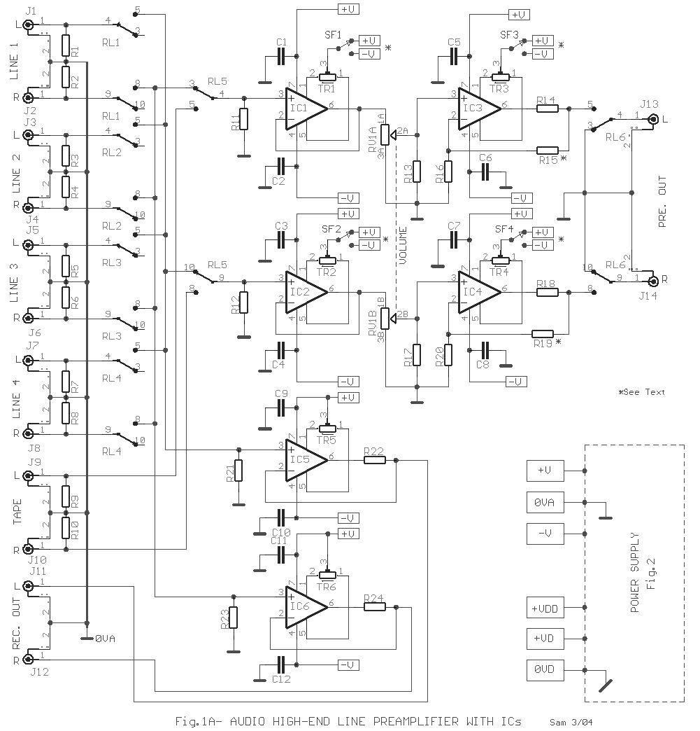
| In the Fig.1A appears
the main body that concerns the sound. In the choice exist my constant preference in the
relay. I believe that it is the better solution, after it offers the better results of use
and sound quality and stability in the time. Of course it depends from the relay quality
that we will use. A lot of good constructors offer the suitable solutions. What it should
we are careful they are closed type and they contain in the packing diode parallel with
the inductor. If we select some type that does not allocate diode parallel with the
inductor then it will be supposed place diodes. All the circuit does not allocate unyoke
capacitor in the road of sound signal, following DC coupling [for this helps trimmers TR1
-6]. The acoustic signal from the input that be selected is directed in the first buffer
stage, that is constituted by two single opamp. IC1 -2. This stage does not offer gain in
the acoustic signal. As you would observe in the drawing, all the opamp. allocate one
small trimmer [TR1 until TR6]. The use these
trimmers us allows the precise Offset voltage adjusting in the exit opamp. in very low
levels [200uV]. Whoever judges that this is excessive, it can them suppress. In each
trimmer they exist jumper switch SF1-4. Each switch selects if the trimmer it�s supplied
by positive or negative voltage line. This depends from the opamp. type that will be used.
If we lead to concrete opamp. type and it will need we change then we can suppress. In
Table 1 appears the voltage polarity with which it should be connected the trimmer
depending on opamp. type. The regulation trimmer should become, after the preamplifier
works few time and with potentiometer RV1 in lowest resistance [closed], without it is
connected some power amplifier in the preamplifier output. The opamp. choices in places IC5 -6 are such in order that the trimmer
connection TR5 -6 becomes exclusively with the positive voltage line. Afterwards the first
stage it follows the RV1 VOLUME potentiometer, which should they are very good quality. It
follows the OUTPUT LINE stage constituted from the IC3 -4. In this stage becomes level
gain of such signal in level so that are drve all the types of power amplifiers. With
values R15 -18=15Kohm and R16 -20=2.2Kohm the gain is roughly 17dB [X7 5]. This gain can
change, if we change somebody from these resistances following the calculation type of
gain A = R14 + R15 + R16 / R16. Resistances R14-18 protect the opamp. exit from
short-circuit as also they make the suitable long cables adaptation. These resistances are
placed in the feedback bronchus, for this reason should they are calculated in the total
gain. In the output exist the contacts of RL6 that close when passes the delay time that
is determined by the C13 and IC7a-b [Fig 1A], so that are not listen annoying noises in
the power supply opening and the closure. Opamp. IC5-6
they function as buffer with X1 gain, driving the Record outputs J11 -12. |
|
Table 1 |
| NE5534 |
+V |
| OPA604 |
-V |
| OPA627 |
+V |
| OPA637 |
+V |
|
|
|
| Opamp.
Choice.
|
| The opamp. choice is a
basic factor for the good reproduction of sound. A cheap, but good solution is the use in
all the places of classic NE5534. The better certain choice are the OPA604, OPA627 and
OPA637 of Burr - Brown but they are more expensive. The OPA637 is Top but it does not
provide stability with gain under X4, hence it is excluded from places IC1-2-5-6 where the
gain is X1. The OPA604 is the better choice because it has too much good characteristics
and is good-value. Is a single fast opamp. that combines use FET but also bipolar
technology semiconductors. It has very low distortion, low noise, big bandwidth, he is
constant in the gain X1 and it can drive 600 ohms loads.
|
|
Part
List Main Preamp. [Fig.1A] |
|
| R1.....R10=47K
ohms |
TR1.....TR6=100K ohms Multiturn Trimmer |
SF1......SF4=Jumper
Switch [See Text] |
| R11-12-21-23=1M ohms |
RV1=2X10K
ohms Log. Pot. [ALPS-NOBLE] |
J1.....J14=RCA
Type Female gold-plated plug |
| R13-17=470K ohms |
C1......C12=100nF
100V MKP 5% |
|
| R14-18-22-24=100 ohms |
IC1-2=OPA604-OPA627-NE5534
[See Text] |
|
| R15-19=12K ohms [See
Text] |
IC3-4=OPA604-OPA627-OPA637-NE5534
[See Text] |
All Registors is 1/4W 1%
Metal film |
| R16-20=1.8K ohms |
IC5-6=OPA604-OPA627-NE5534
[See Text] |
For ICs Techical Data see my
Database |
|
| . |
|
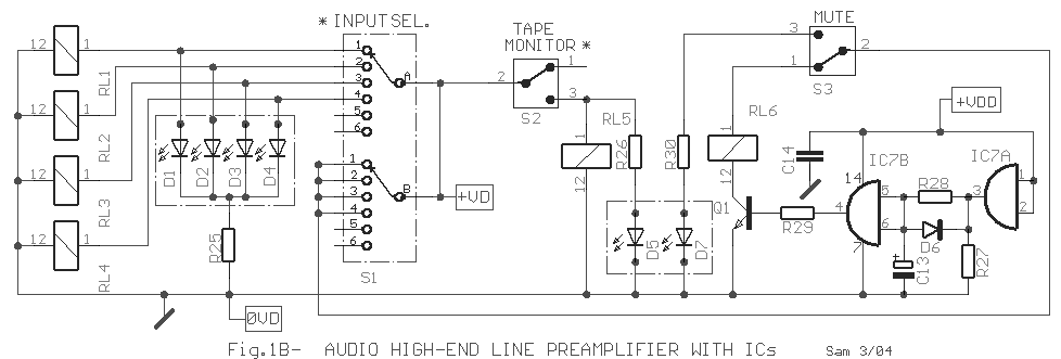
Input
Selector and Delay Time [Fig.1B] |
|
|
|
| Input
Selector -Delay output connection [Fig 1B] |
| Here exists the circuit of inputs choice relays from the S1, Tape monitor
from the S2, MUTE from the S3 and the delay output connection circuit [IC7A-B]. With the
S1A supply with + 12V [+ VD] the corresponding relay. Simultaneously turns on also the
corresponding Led D1�D4, so that we know who entry we selected. In the same simple
operation is supported also the choice Tape monitor. When we supply the preamplifier with
supply, the +VDD supplies IC7A his exit becomes High, via the R28 charge capacitor C13,
after 5 seconds the exit of IC7B
becomes High, the Q1 closes also the
RL6 arm. If you want to change this time it will be supposed you change the
value of C13 with different from the one that I give in the part. To it�s the circuit
simplest operation MUTE becomes with the S3 as follows. In the normal place the S3 is
closed. When select operation MUTE the switch open is interrupted the supply to the RL6
which the contacts open so that is interrupted the flow of signal to the preamplifier
exit. Simultaneously turns on the D7 Led, showing MUTE operation. Closing again the S3 the
supply is restored immediately and the contacts of RL6 closes, whenever the acoustic
signal drive again the power amplifiers. As you observe the second contacts team of S1
they are jump and via these becomes the supply of + 12V in the S3. This ensures that each
time the S1 rotary switch moved by a place in the other exist small time supply pause of
RL6 with +12V [+VD]. Thus each time where it become the choice of some input, the exit of
preamplifier is interrupted with result likely noises, are not listen. |
| . |
|
Part
List Sel. and Delay [Fig.1B] |
|
|
| R28=1M ohms |
C14=100nF 100V MKT 5% |
RL1.....RL6=Relay 12V [See Text] |
| R25-26-30=1K ohms |
IC7=4081
c-mos |
S1=6 stepX2
contact Rotary Switch [See Text] |
| R27=10K ohms |
D1.....D5-7=Red
Led 3mm |
S2-3=1X2 step mini switch |
| R29=39K ohms |
D6=1N4148 |
All Registors is 1/4W 1%
Metal film |
| C13=4.7uF
25V |
Q1=BD678 |
For ICs Techical Data see my
Database |
|
|
|
|
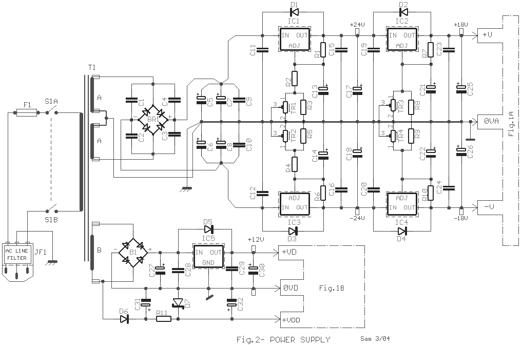
| Power
supply. |
| Essential condition
for a high-End preamplifier, it is accompanied with proportional quality power supply. In
the input of network supply exist JF1 plug that contains also filter EMI. Exist different
supply circuit, for the sound section and the relay section, completely separated with
different ground line. In the sound circuits section select the solution of double voltage
stabilization. This topology creates a very powerful filter, which ensures very good
ripple reject and noise results. Simultaneously it ensures small degree thermic and
mechanic regulators fatiguing in the duration of time. The output voltage regulation of
stabilizers becomes with multiturn trimmer that exist in each regulator. All the
regulators should be placed in small heatsink. Regulator IC6 is not adjusted but constant
out voltage +12V. In the relay supply line don�t want something more. The use in the
place of C31-32 capacitors with small capacity ensures fast uncharged at the main supply
closure, so that opens fast the relay RL6 disconnect the preamplifier output. Thus no
noises from uncharge of supply capacitor does not pass in the power amplifiers. The Zener
D17 in combination with the R11 they create a voltage stable +12V so that is supplied the
IC7. Transformer T1 good it is placed as long
as more far it becomes from the sound circuits. |
| . |
|
Part
List For Power Supply [Fig.2] |
|
|
| R1-6-7-10=170
ohms |
C27=470uF 25V |
TR1.....TR4=10K
ohms Multiturn Trimmer |
| R2-4=3.3K ohms |
C30-32=4.7uF 25V |
T1=230Vac
@2X22V 50VA //12V 5VA |
| R3-5-8-9=15K ohms |
C31=47uF 40V |
S1=2step
2contact Switch [230Vac 3A] |
| R11=2.2K ohms 1W |
B1=Bridge Rectifier 80V-3A |
F1=1A Slo
Blo Fuse |
| C1....C4=22nF
100V MKT |
B2=4 Diodes 1N4002 |
JF1=3pin male supply jack with EMI Filter |
| C5.....C8=4700uF 63V |
D1.....D6=1N4002 |
|
| C9-10=1uF 100V MKT |
D7=12V 0.4W Zener |
|
| C11-12-15-16-19-20-28-29=100nF
100V |
IC1-2=LM317T
[On Small Heatsink] |
All Registors is 1/4W 1%
Metal film |
| C13-14-21-22-25-26=10uF 25V |
IC3-4=LM337T [On Small
Heatsink] |
For ICs Techical Data see my
Database |
| C-17-18=100uF 40V |
IC5=LM7812 [On Small
Heatsink] |
|
|
| . |
|
|
|
|
Sam
Electronic Circuits 3/04 |
|