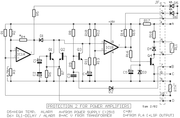
The circuit protection output of power amplifiers and loudspeakers, dispose certain
interesting elements, as the isolation of loudspeakers from the exit of amplifier, when is
presented continuous voltage in his exit or when the temperature of heatsink, goes up
excessively, providing simultaneously and time delay in the connection loudspeakers in the
amplifier, so that we avoid pass in them, the known annoying noises from the charge -
discharge of capacitors of supply. It�s constituted by a binary comparator [ IC1 ], the
transistors Q1-2 and indicative LED D5-6. The supply of circuit can become from positive
voltage [ Point A ] of mainly power supply, which is stabilised by the D3 and the R17, in
+ 15V. Point B is connected in one of the secondary AC coil of main transformer. If close
the main switch of main line AC, then a AC voltage (in secondary coil of transformer), is
presented in the point B, it�s rectified from the D2 and it supply with negative
voltage, via the R9, the Q3, this cut off and it begin charge the C4 via the R10-11. As
long as time therefore last the charge of capacitor, the input [+] of comparator IC2B is
found in low level concerning input [-]. The exit of IC2B, has low level, therefore the Q4
remain in cutt off and the RL1 remain deactivate, the D6 he is ON. Just the C4 charged,
change the situation of IC1B, is activated the RL1, the loudspeaker are connected in the
amplifier output, the D6 it OFF. When it�s interrupted the supply, all the process is
inverted, and the loudspeaker disconnect, without pass annoying noises. If as long as it
work the circuit, is presented problem of continuous voltages in the exit of amplifier
then turn off of RL1 and protected the loudspeakers. This become with help the Q1-2. The
acoustic signal from the exit of power amplifier, is led to point D, the alternate
voltages is led to the ground via the C1-2, that create a not polar capacitor. Continuous
voltages, bigger than + 1.7V or smaller than �4.8V, activate immediately the Q1 or the
Q2, respectively. With the activation of transistors goes down the level of input [+] of
IC1B, so that turn off and the RL1. A other section of protection that for us provide the
circuit is the thermic protection. This become with the help of sensor temperature the
RTH, which is a resistor of type PTC (positive factor of temperature), and is found placed
above in heatsink, where are found also the power transistors. Her price increase, with
the increase of temperature, until the potential in input [-] of IC1A, goes up above from
the level of input [+], which is determined with the voltage divider R2-3. As soon as the
level in input [-] exceed the level of input [+], the exit of IC1A, it return in low
level, compelling and the IC2B to change situation, turn off the RL1 and to turn on the
D5, that show the thermic protection. In the circuit the limit above which it exist clue
of thermic protection they are 70?C. If it�s presented instability, in this stage, in
operation of RL1, should be changed the R4, with other of smaller price. The circuit was
published in magazine �Elektor� 12/95.
|
