�
������������ ��� �������� ��� �����, ����� ����
������ ����������� ������������, ��� ��� ������
�� ��� ����� ��� ��������� �� ���� � [Class
A].
��� ���� ������� ����������� ����������, ����
������������ ������������ ������, ���� ��
���������� �� ����� ���� ��� ������. ��� ������
������� ����� � ����� ������������ ���������� [Q1,2]
��� ���������� ���� ��� ���� ������� ��
���������� ��
������� ��� ���� �������������� �� �����
''������''. ������� �� ��������������� ��� ����
���������� ���� �� BC550C ��� BC560C, ����� ��
������ ���� ���� �� ''����������'' ����� ��������
�� ����� ��������������. �� �� TR1 ��������
��� ��������� �� ���������� ��� ���� �������� [Offset] ����
����� ��� �������. ������ ���� �� ���������� ���
�� �������������� �� ��� ����������� 82� ��� ����
��� R6-7. ���
������ ��� ������ �� ������ ����� ��� �� ������ D1 ��� D2 ������ ��
������������ ���� ����� ��� ���������� Q3 ��� Q4
����������, ���� �� ����� ����� �������
�����������. �� ���� ������ �� ����� ��� �� ��
���������� Q8-Q10 ��� Q9-Q11
����������. � ������� ��� �������� �������
������� �� �� TR2, ��� 20mA ���
����������� �� ����� ����� 200mV, ��� ����
��� ���������� R25. ���
������� � �������� ��� ������� ���� �������
���������� �� ����� ������� ������ ��
��������������� ��� ������� C12 � �� ���
������������. �� ������� ��� ��������� ��
������� �� ������� ������ ��������� ��� �����.
���� ������ 1 �������� �������� ������ ��� ����
������, ��� �� ��������� ���� �������.
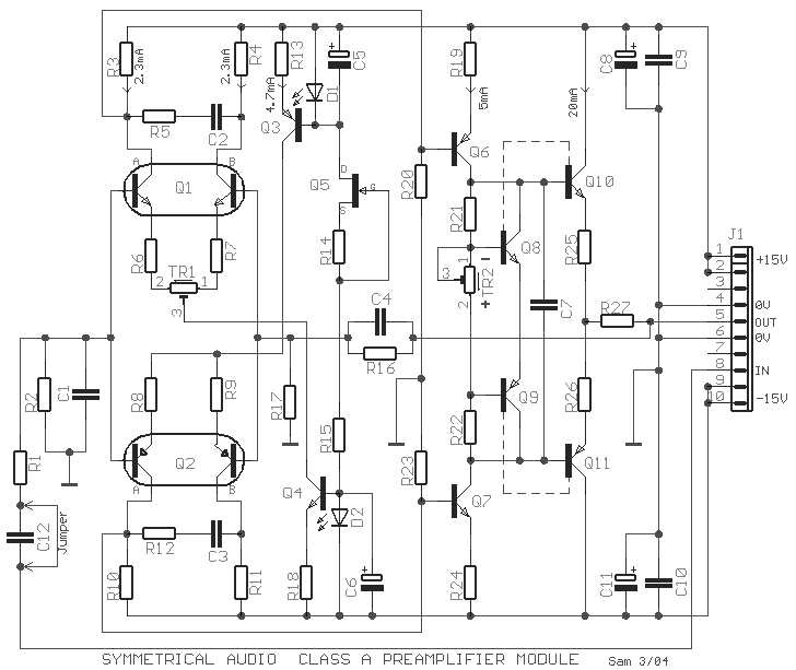
The
preamplifier that appears in the figure is a completely symmetrical preamplifier, from the
input as the exit and it works in Class A. It does not have somebody innovation, simply it
uses good solutions, in order the result is what should. Such proposal is the use
transistors matched [Q1, 2], that finds in the same chip with result the
thermic and other characteristics are ''perfect''. It can they are replaced by simple
transistors as the BC550C and BC560C it's enough you enter in the fatigue to matched you
pairs with similar characteristics. With the TR1 we can if it needs we regulate the Offset
voltage in the exit of unit. It can however be suppressed and it's replaced with two
resistances 82 ohm in the place of R6 -7. A point that it should I accent it's that diodes
D1 and D2 it should they are placed very near in transistors Q3 and Q4 respectively, so
that they have common thermic behavior. The himself should become also with transistors Q8
- Q10 and Q9 - Q11 respectively. The regulation of out current becomes with the TR2, in
20mA that corresponds in 200mV fall across resistance R25. If we want the response of unit
in the low frequencies she becomes ''flat'' it should jumper the capacitor C12 or him we
abolish. The currents that run through the circuit in various points appear in the figure. In table
1 exist various voltages in utmost materials that they will help in the regulation.
|
