��� ����
���� �������, ��� �� ���� �������� ���� ���������
��� ����� ����� �������� ������������� ����� ��
��� ���������� ������ ��� �� ������ �� ������ ���
������ ��� ���� ����� �������. ���� ��� ��
��������� ������ ���������. ���������� ������ ��
����� ��� ��� ��� ������ ������������ ��� �����
�� ����� ������, ��� ��� ������� ���������� � ��
������ ������ ��� ��� ����� ���� �������� ��
�������� ��� ��������� �� �� ��������. �������
��� ������� ��������� ������ ��� RL1 ���
���������� ���� J2, ��� ������ �������� ��
��������������� ���������� ���� ����� �������
������. � ���������� ������ ��������� ��� J1, ��
����� ���������� ����� ������. ���� �� ��������
����� ������� ���� � ���� ��� ������� ����� 48-50VDC
�������. ���� � ���� ��������� ��� ��������� ���
���� �� ���������� ��� IC1, �� ����� ����������
���������� ��� �� ������� ��� ��� ����������
������. �o �������������� ��� IC1 ����� ���� ��
��������� ON � ������� ��� IC2A ����� LOW [L] ��� �
������ HIGH [H]. ��������� ��� ���� �� �������
������������ D6, R4, R5, C1, � ������� ��� IC2B ����� ���
���� HIGH ��� � ������ ����� LOW, �� ���������� Q1
����� OFF ��� � RL1 ����� �����������������. ���� ��
��������� ��� ��������� �������, ���� � ���� ���
����������� ������� ������ ��� 6-10Vdc. ��� �
����������� ��������� ������������� ��� �� RL1,
�����������. �� �������� ��� ������������� �����
�������� � ������� ������� ��������, ������ ��
�������������� ��� RL1 ���� ��� �������� ���
��������. �� �� �������� ������������ ���
������� ������� ���� ����� IC2A ��� ���� IC2�,
������������ ��� ������� ��� ���������� ����
������ ��� IC2B, �������������� ���� �����������
���� ���������� ��� RL1. ��� � R4=100K ���� �� RL1
�������������� ���� �� �������� ����������� �
���� �� ��������� ����� ��������. �������� �� �
R4=1M, ���� �� RL1 �������������� ����� ���� ��
��������� ����� ��������. � ���������� ���
���������� ������� �� ��� ���� �������
�������������� ��� +12V.
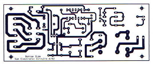
A very simple
circuit, that will find application in the case where you have a lot of telephones
installed on a telephone line and would want to know if somebody of them is open. Thus you
will not be off any discussion. Simultaneously it can cut the certain sound from stereo
amplifier that are in high volume, the sound of some television or turn on some light the
night when it ring the telephone and needs him you raise. Exists a pair of free contacts
of RL1 that connects to the J2, which you can use connecting there any appliance you want.
The telephone line connected in the J1, with what polarity you wants. When the telephone
is closed then the line voltage is roughly, 48-50Vdc. This voltage turn on the photodiode
and this, the transistor of IC1, which it simultaneously isolates, the circuit from the
telephone line. The phototransistor in IC1 are now in situation ON, the input of IC2A are
LOW [L] and output HIGH [H]. Ignoring for little the circuit of delay D6, R4, R5, C1, the
IC2B input, are also this HIGH hence the output are LOW, transistor Q1 are OFF and the RL1
are deactivate. When the telephone earphone is raised, then the telephone voltage line
fall in 6-10Vdc. All the previous situation is reversed also the RL1, turn on. The
telephones that use for dial choice, disk or pulse system, can they open and close the RL1
at the duration of choice. With delay network, that exist between in gates IC2A and in the
IC2B, we delay the situation changes in the input of IC2B, ensuring thus stability in the
operation of RL1. If the R4=100K then the RL1 is activated when the telephone ring or when
the earphone is raised. On the contrary if the R4=1M, then the RL1 is activated only when
the earphone is raised. The circuit supply becomes with a simple regulation circuit, in +
12V.
|