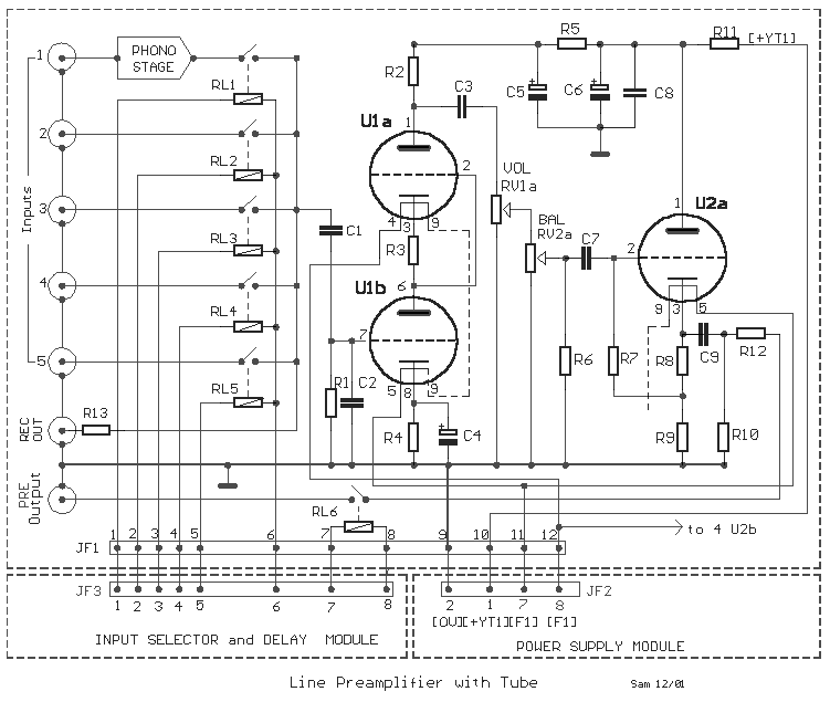
Fig.1 |
| The interest for circuits
of tubes, remains big. Thus I will give completed in enough big degree, circuit of
preamplifier. It is mainly constituted by the department of main
preamplifier, the department of input selector, delay
of application voltage and connection output of preamplifier with the final amplifiers and
the department power supply. The department of mainly preamplifier
appears in the Fig.1. Deliberately it does not have something revolutionary in the
designing. In the entry exists a simple circuit constituted from relay that is drive from
input selector [S2]. The signal afterwards drive to the next stage
that is constituted by a circuit cascade S.R.P.P (shunt regulated push�pull) and a
circuit cathode repeater, in the exit. As S.R.P.P used the double triode ECC82 (U1a-b), in
connection ��series �� of two triode, with characteristically pentode . The
circuit was used as department of input R.F, in the old televisions with tubes, offers big
input impedance and very good response in the high frequencies. In the circuit preferred
use capacitors with big capacity in various points and capacitors of polypropylene or MKT.
in the exits of tubes, for better quality of sound and response in low frequencies. Exists
a simple circuit for the VOLUME and BALANCE potesometer, that is should be very good
quality. In the exit exists a circuit Cathode Repeater, that is constituted by the half
department of tube ECC81 (U2a). Here exists a particularity. Whoever wants it can use the
one of half tube for a other channel and half for the other channel. We can however use
his other half tube of channel, leaving him inutile, placing a output tube for each
channel. This becomes in order to we avoid his effect of channel in the other, if we use
the same tube ,for two channels. It�s known that the tubes, do not have very good
separation, when find itself the two departments, in the same integument. The choice is
yours. In this stage are found also the contacts of RL6, who
connect the exit of line preamplifier in the final amplifier, with such certain time
delay, so that are not heard annoying noises, when open or close the preamplifier. The RL6
closes after have been stabilised and applied, all the voltages of circuit. All the relay
of SEL. and OUTPUT, should be very good quality. The circuit of control appears in circuit
SEL - DELAY, (Fig.2). .
|
| R1-7=1Mohm |
R12-13=100ohm |
C9=4.7uF 250V* |
| R2=100Kohm 1W |
C1=220nF 250V* |
U1=ECC82 |
| R3-8=1Kohm 1W |
C2=220pF ceramic or mylar |
U2=ECC81 |
| R4=1.2Kohm 1W |
C3=2.2uF 350V* |
RV1=2X100Kohm
log. |
| R5-11=5.6Kohm
2W |
C4=1000uF 16V |
RV2=2X100Kohm
lin. |
| R6=100Kohm |
C5-6=2X50uF 450V |
RL1....6=Relay 12V 2X2 [1A] |
| R9=22Kohm |
C7=1uF 250V* |
|
| R10=100Kohm |
C8=220nF 630V |
*polypropylene or MKT |
|
Input
Selector - Delay Drive |
|
|
|

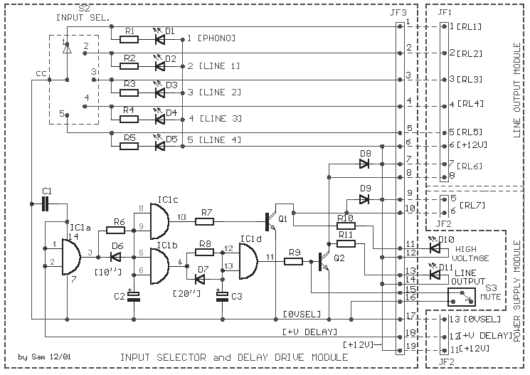
Fig.2 |
In the
Fig. 2, you see the department that concerns the control of input sel. relay and the
circuit of time delay. The drive of inputs choice Relay becomes from selector S2, that
drive the corresponding Relay (Fig. 1), via the JF3/1�..6.
Simultaneously we have optical clue of choice from corresponding Led (D1�. D5). The
circuit is exceptionally simple. In the second department of Fig. 2, exists the circuit of
time delay, round the IC1. The first delay time (10��), with R6, C2, concerns the
control of RL7 that give the high voltage, in the circuit of line
preamplifier. This becomes in order to is applied the high voltage, after first, heat the
filament of tubes. The control of RL7 becomes from the Q1, JF3/9-10 and the optical clue
becomes from LED (D10). After close the RL7 and is given the high voltage then, after a
time delay that is determined by the R8, C3 (20��), the Q2 conduct and drive the RL6 via the JF3/7-8, in order to it connect the exit of
preamplifier in the final amplifier. Optical clue of this operation becomes from LED
(D11). With switch S3, when it needs, drive the base of Q2 to 0V, it open the RL6, so that
is cut the sound signal to the exit, without close preamplifier (MUTE). The circuit is
supplied by two voltage. The voltage + 12V, that supplies the Relay and the voltage + V
DELAY, which supplies the IC1. This segregation will be explained in the circuit power
supply.
|
| R1.....5=1.2Kohm |
C2=10uF 25V |
Q1-2=BD679 |
| R6-8=1Mohm |
C3=22uF 25V |
IC1=4081 |
| R7-9=10Kohm |
D1......5=3mm Red LED |
S2=SEL 1X6 step |
| R10-11=1.2Kohm |
D6......9=1N4148 |
S3=1X2 mini switch |
| C1=100nF 100V |
D10-11=3mm Green LED |
|
|
|
|

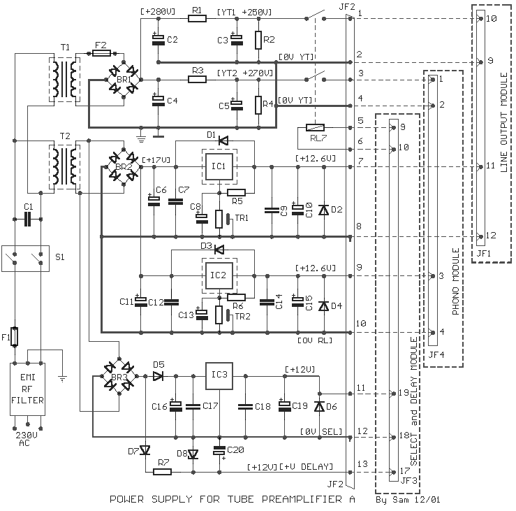
Fig.3 |
In the
Fig. 3, appears the circuit of power supply. He�s also simple in the design. We can him
separate in the department that are reported in the benefit of high voltage and the
department benefit of low voltage, for the filament of tubes and the circuit of delay and
control Relay. Exist two transformers, for high voltage and low voltages (in plate). This
solution was preferred for reasons of tumor. In the department of high
voltage, we have the separation of voltage in two parts. To the line preamplifier and
the other to preamplifier PHONO. This becomes, because somebody it can want use in his
preamplifier unit PHONO. In line with the high voltage supplies exist contacts of RL7,
what are drive by the circuit of delay and they close that exists the
essential time delay in order that filament reach in good temperature. In the department
of low voltages, exist and here separation of control of filament, with regulated
continuous voltages [ IC1-2 ]. This becomes clearly for reasons of
resolution of provided power. The IC�s that regulates the voltage of filament, it should
they are placed without fail in heatsink. Their regulation should become first without
load, in the exit (after we place a resistance 1.5K 1W as load, which we remove afterwards
the end of regulation) and afterwards with complete the load of filament. In the
department supply of Relay and delay exist resolution of voltages, in two parts. A part
via the regulator + 12V [IC3 ], supplies the Relay. A other sector
via the D7, R7, D8, C20 supplies the IC1 [ Fig. 2 ], with a voltage +
12V, stabilised from zener D8. This resolution becomes because the voltage [+ V DELAY ],
should '' fall '' very fast, in order that cut also the Relay fast, when we close the main
line of supply. This is the reason that the C20 is small in capacity. The block diagram of
connections of mainer voltages, appear in the Fig.3. A point that it will be supposed you
are careful they are, that the lines of 0V, are separated and are not met between them, in
no point, neither are drive to the earth, only that the 0V of high voltage. The choice of
unit of preamplifier PHONO can become from you.
My proposition is: Tube
PHONO Preamplifiers with ECC83
|
| R1=2.2Kohm 5W |
C8-13=10uF 16V |
IC3=7812 [1A] |
| R2-4=100Kohm
2W |
C10-15-19-20=47uF 25V |
T1=230Vac / 200V 0.15A |
| R3=680ohm
5W |
C16=470uF 25V |
T2=230Vac / 12V 3A |
| R5-6=220ohm |
C17-18=100nF 100V |
F1=0.2A slow |
| R7=470ohm
1W |
BR1=4 X 1N5408 |
F2=0.1A fast |
| TR1-2=4.7Kohm
trimmer |
BR2=4 X 1N5408 |
S1= Switch 2X2 10Aac |
| C1=33nF 630V |
BR3=4 X 1N4007 |
RL7=12Vdc Relay 2X2 10A |
| C2.....5=2X50uF >350V |
D1.....7=1N4007 |
EMI RF Filter 230Vac/6A |
| C6=4700uF 25V |
D8=12V 0.5W zener |
* with heatsink |
| C7-9=100nF 100V |
IC1-2=LM317* |
|
|
Sam
Electronic Circuits 12/01 |
|
|


