Ένα
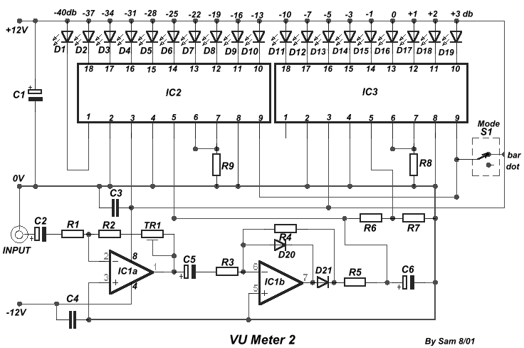
κύκλωμα μέτρησης στάθμης βασισμένο πάνω σε μια
τυπική εφαρμογή της National. Το κύκλωμα γύρω από το
IC1 κάνει προσαρμογή εισόδου και ενίσχυσης με το
τρίμμερ Tr1. Το κύκλωμα γύρω από το IC2 κάνει
ημιανόρθωση ακριβείας του ακουστικού σήματος .
Με τον διακόπτη S1, επιλέγουμε το είδος της
ένδειξης που θα έχουμε από τα LED. Με τις τιμές στις
αντιστάσεις R6 και R7 που υπάρχουν στο κύκλωμα, η
στάθμη του σήματος , στην είσοδο είναι 7.8V (κέρδος
πρώτης βαθμίδας IC1, μονάδα), και η διαφορά στάθμης
μεταξύ των LED D10-D11 πρέπει να είναι 3 db. Το θετικό
τμήμα της τροφοδοσίας πρέπει να έχει την
δυνατότητα να δίνει περισσότερο ρεύμα, μιας και
επιβαρύνεται με το ρεύμα των LED.
A circuit of
measurement of level based on a typical application of National. The circuit round the IC1
makes input adaptation and amplification with the trimmer TR1 [GAIN]. The circuit round
the IC2 makes half-wave rectification of acoustic signal. With switch S1, we select the
type of indication, that we will have from the LED. With the prices in resistances R6 and
R7 that exists in the circuit, the level of signal, in the entry is 7.8V (gain of first
stage IC1, is one), and the difference of level between the LED D10-11, should are 3 db.
The positive department of supply, should have the possibility of giving more current, one
and it is overloaded with the current of LED..
|
