����
����� ������ �� ���������� ������� WIEN,
���������������� ��� ��� �������� ����������
������� ���� ������� ����������. ������
������������ ��� ���� �������� �������
����������, ���� ����� ������������� ������ ���
�������� ����������. ���� ������������ �������
������� WIEN �������� ��� Fig. 1. �� �������� ���
������� ����������� ������ ��� ���������
�����������. ���� ���������� ��������� ���
���������������� ����� ����������� ���
��������, � ��������� ���������� ����� : F=1/2�RC
(1). � �������� ��� �������� �������� ��� ��
�������� ��� ��������� ����������� ���
������������ ��� ��� �����: A=RA+RB/RA (2). ��� ��
����������� �� ����������� ��� ��������� �� ���
������������ �� ���� ������, � �������� ���
�������� ������ �� ����� ���� ���������� ��� ���
���������� ��� ���������� �� �������� ���
������� �����������. ���� ��������� ���
���������������� ����� ����� ����������� ���
�������� ��� ����� ��� ������� ��������� , �
�������� ������ �� ����� ������� 3. ���� ����� , �
������� ��� ��������� ���� �������������� ����
������� ��������� �� ��� ������� ���� ��
��������� ��������� (������� ����������� ,
���������, � ���� ��������� �������), ���
������������� ���� ����� ��� ���������
�����������. ��� Fig. 2 �������� �� ������� ���
��������� . � ��������� ���� ��� �������� ��
������� DC. � ����� ������� IC1 ����� ����
���������� ��������� . � ������� , �������� ���
�����, ������������ ��� ��������������
���������� Q1- Q2, �� ���������� �������, ���
��������� ���� ��������� �� �������� ������ ,
���������� ��� 50�. �� �� �������� �������� ���
���������� ��� ��� �������� ������� ��� ��������
, ������������ ��� ��� ��������� ��������� D1-2 ���
R1. � ����� ��� R1 ��������� ���� ������� ���������
��� �� ������������ ��� ���������� ��� �������
�� ������ ������ ��� ����������� (1-5%), ��������
��� �������� ��� ���������� ��� ����� �� ���
������. � ��������� ��� ����������� ������ ��
������� ��� ���� 20���, ����� �� ������� �
����������� ��� �� ������� ���������� ��� ���
������� ���������� ,����� � ������� �� ����� DC. M�
�� ����� ��� ���� ���� ������ ������ , �
���������� ������� ��������� 1���. � ���������
������ �� ������� , ���������� ��� ����� ���
����������� ��� �������� , ������������ ����
���������������, ����� �� ���������� ��� �����
R1=R2 ��� C1=C2. � ������������ ��� ��������
������������ ��� ��� ���� F=1/2�RC ���� F �
���������� ���������. �� ����� ��� ������� ��
������� , ���������� ������ 10 ��� 50 mA, ���� ��
������ ����� 50�. � ���������� ����� ����������
+/-9V ��� ������ �� ����� ��� ��� ��������� � ���
��� ���� ��������������� �����������. ��� ��
���������� ��� ��������� ������ ��
���������������� ���� ���������� , ���� ��
�������� ��� ����������� , ����������� ��
������� TR1, ��� ���� ����� ��� ����������� ,�� ���
�������� �����������. ��� ��� �������
�����������, ���� ���� ����������� ��� ���������
47� �� ����� �� ��� ����� ��� ��� �������� 8� /0.5W.
������������ �� ������� TR1 ����� �� ��������� ���
��������� ��� ��������, ���� �� ������������
���� ����� ��� ������� ��� �������.
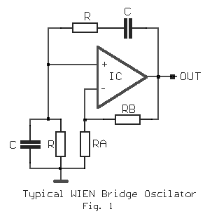
As it is
known the oscillators of bridge WIEN, they are used for the production of sine wave
signals in the low frequencies. Basically they are constituted from amplifier of low
frequencies, in which is created positive and negative feedback. A simplified circuit of
bridge WIEN we see in the fig. 1. The positive feedback it fixes the frequency of
oscillations. In the simpler case where are used same resistances and capacitors, the
frequency of oscillation is: F=1/2�RC (1). The gain of unit is fixed
from network the negative feedback and is calculated by the relation: A=RA+RB/RA
(2). To are maintained the oscillations and together is not distortion the output
signal, the gain of stage should be little bigger than the demotion that it creates
network the positive feedback. In the case where are used same prices of resistances and
capacitors in the sector of positive feedback, the gain should are roughly 3.. In the
practice, the regulation of gain in the predetermined price becomes automatically with the
help of not linear element (lamb of glow, thermistor, or other suitable circuit), that is
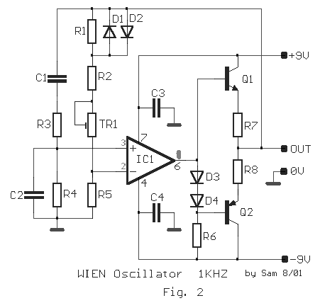
interfered in network the negative feedback. In the fig. 2 we see the circuit of
oscillator. The amplifier has two units in coupling DC. First unit IC1 is a IC amplifier.
Second, constitutes the output, it includes two complemental transistors Q1- Q2, in
symmetrical provision, that allows in the oscillator to drive loads, bigger than 50R. The
not linear element that needs for her automatic regulation gain, is shaped by parallel
combination D1-2 and R1. The use of R1 at parallel in the diodes, decreases the not
linearity of combination and it keeps in low level distortion (1-5%), proportionally the
various of parameters that have the two diodes. The frequency of oscillations can increase
itself until their 20KHZ, without is increased the distortion and is decreased
respectively until the low frequencies, is enough the coupling is DC.. With the materials
that I give in the table of materials, the oscillator produces frequency 1KHZ. The
frequency can change, if changing the prices of resistances and capacitors, avoiding them
electrolytic capacitors, it is enough we keep relation R1=R2 and C1=C2. The capacity of
capacitors is calculated by the type F=1/2�RC where F the produced frequency. The
current that pulls the circuit, oscillates between 10 and 50 mA, when the load is 50R. The
supply is � 9V and can becomes from two batteries or from one
simple stabilised power supply. In order to we regulate the generator it should we use a
oscilloscope, where we will see waveform, regulating him trimmer TR1, until we see the
waveform, me the less distortion. If it does not exist oscilloscope, then simply we place
a resistance 47R, in line with the exit and a loudspeaker 8R/0.5W. We adjust the trimmer
TR1 until we hear the oscillation in the loudspeaker, but advance little still the
regulation trimmer..
|