High-End
Audio Modular Preamplifier |
This preamplifier is requirement result of many friends
to give a high quality preamplifier, capable to drive high quality power amplifiers with
good sound, it's not however difficult to making, it combines simplicity and handiness. It
does not allocate a lot of facilities and various filters, but is drawn so the acoustic
signal follows the smaller course without it's influenced by stages they do not need, with
result the coloration of reproduced sound. It follows the modular philosophy that gives
the possibility of changing each module and adapted in yours acoustic taste. Thus it will
constitute the base for long-standing listening and experimentations. Use relay in the
input selection ensures the smaller way and the better possible quality, because the relay
contacts are not influenced easily by temperature changes and environment, offer smaller
ohmage and parasitic resistance in the signal course. This of course depends also from the
relay quality that you will select; I propose choice of relay small size and very high
quality. Enough companies they manufacture such relays. Exists different possibility of
choice for the Listen inputs and different for the analogue recording. Thus we can listen
other sound source and other recording. Exists the possibility, for those who they judge
of suppressing Balance potesometer [RV1], the recording selector and proportional relays
making the manufacture simplest and more economic. In the each place module we have big
variety of choices. Certain you I will give I below, but can make also your choices. As
you will observe exist somebody "facilities" as monophonic [MONO] operation etc. |
| . |
|
|
|
|
|
|
| Discription |
The choice of
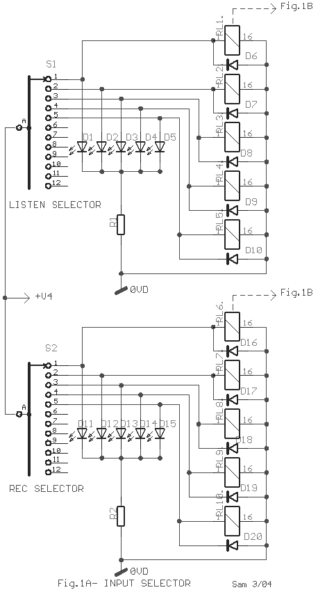
acoustic signal follows two streets [Fig.1A]. First with the selector S1 that is 1 contact
12 places, from which I use five. Exists the possibility to using also the remainder
places adding to them proportional relay and Led. Each place supplies the proportional
relay and Led that it shows whom input has been selected. The supply becomes with + 12V
[+V4]. Selector S2 functions with the same way as the S1, supplying them proportional
relays and Led, so that becomes the source choice that recording. Afterwards recording
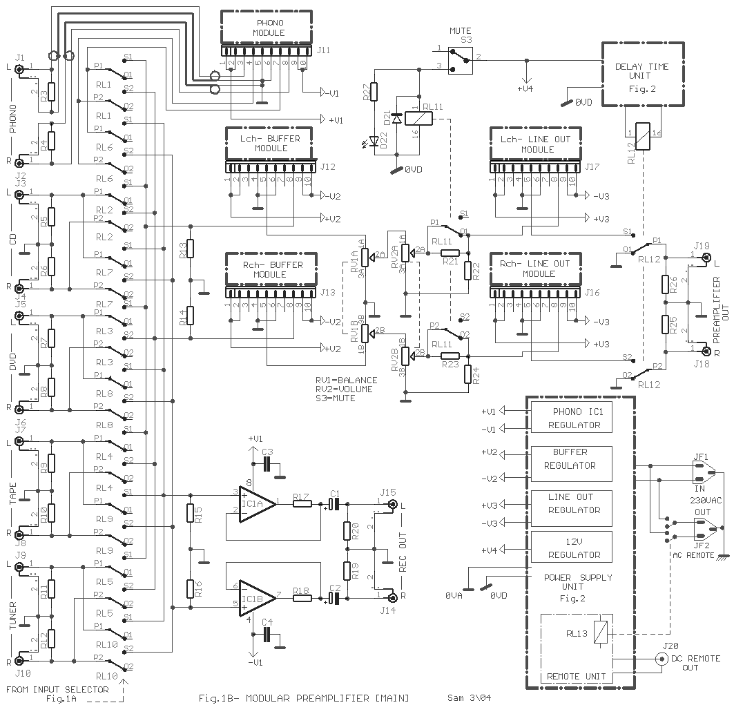
relay exists the buffer unit round IC1 [Fig.1B]. In the part list exist certain choices
for opamp. that will undertake this role, but exists the possibility of selecting somebody
of your choice. All the inputs are high level apart from input PHONO [RIAA Filter] that is
directed in proportional module PHONO [J11] and by his exit return again in the block
selector relay. He is alone module that has stereophonic structure and the two channels
that abut to connector [J11]. Those who do not allocate the old turnable [pick-up] and disks
collection of 33 turns, they will not need PHONO module. It can easily they change him in
line, suppressing connector J11 and you connect the corresponding inputs J1-2 in
proportional contacts P1-2 relay RL1-6. The relay team of listening direct the
stereo acoustic signal from some input in Buffer module [J12-13]. The gain of this unit is
X1, does not provide no gain in the signal. They follow potesometer BALANCE [RV1a-b] and
VOLUME [RV2a-b] that regulates the balance and the level of acoustic signal respectively.
These two Potentiometers should be high quality also from acquaintance constructor.
Afterwards the Potentiometer VOLUME exist the MUTE stage that is constituted by a divider
R21-22 and the contacts of relay RL11 that are found parallel with the R21. In normal
operation the contact jumper the R21, the signal pass without fall. If it close switches
S3, turns on the D22, the RL11 arms, the contact opens and the R21 with the R23 they
configure an divider which create a fall of level in acoustic signal [-20dB]. The same
logic is also for the other channel where exist the resistors R23-24. In the continuity
the acoustic signal enter via the J16-17 in Line module what offers the suitable gain in
the signal and this drive all the goods power amplifiers. Then exist the contacts of RL12
that the operation of is described in the delay circuit. |
| . |
| ��������
��� �� module PHONO |
|
|
|
|
 Phono RIAA Preamplifier 1 Phono RIAA Preamplifier 1 |
 Phono RIAA Preamplifier 2 Phono RIAA Preamplifier 2 |
| . |
| ��������
��� �� module BUFFER |
|
|
|
|
 Class A buffer amplifier [My choise] Class A buffer amplifier [My choise] |
| . |
| ��������
��� �� module LINE OUT |
|
|
|
|
 Symmetrical Audio Class A
preamplifier3 [My
choise] Symmetrical Audio Class A
preamplifier3 [My
choise] |
 Symmetrical Class A [1] Symmetrical Class A [1] |
 Symmetrical Class A [2] Symmetrical Class A [2] |
 Class A Line preamplifiers Class A Line preamplifiers |
| . |
Part
List for Modular Preamplifier [Fig.1a-b] |
|
| R1-2-27=1Kohm metal film 1% |
C1-2=10uF 25V |
IC1=TL072
- NE5532 - OP275 |
| R3-4=100Kohm metal film 1% |
C3-4=47nF 63V MKT 5% |
S1-2=1X12 step Rotary Selector |
| R5-6-7-8-9-10-11-12=47Kohm metal
film 1% |
RV1=2X22Kohm Lin. Pot. [Alps] |
S3=1X2
step mini switch |
| R13-14-15-16=1Mohm metal film 1% |
RV2=2X10Kohm Log. Pot. [Alps Black
or Blue] |
RL1....12=12V 2 places 2 contact
[Finder -Omron] |
| R17-18=100ohm metal film 1% |
D1-2-3-4-5=LED Red 3mm or your
selection |
J1......10=RCA Type Female
gold-plated plug |
| R19-20-25-26=100Khom metal film 1% |
D6-7-8-9-10=1N4148 |
J11-12-13-16-17=10pin Gold Female connector 2.54mm step |
| R21-23=100Kohm metal film 1% |
D11-12-13-14-15-23=LED Red 3mm or
your selection |
J14-15-18-19-20=RCA Type Female
gold-plated plug |
| R22-24=10Kohm metal film 1% |
D16-17-18-19-20-21=1N4148 |
For ICs Techical Data see my
Database |
|
| . |
|
Power
supply-Delay time and Remote Unit |
|
|
|
| Power Supply and
stabilisation. |
A good
preamplifier should essentially be accompanied from one good power supply. Thus I
preferred the solution of separate voltage and stabilisation of each stage, separately.
This does not allow in the various units' influences the one the other via the supply,
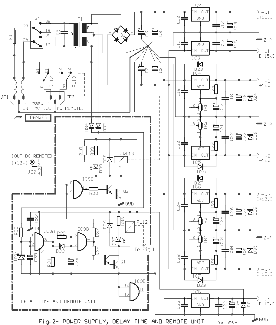
ensuring lower distortions and better transient response. In the input of 230Vac exists
the plug JF1 that contains filter of reject parasitic voltages. Transformer T1 it should
they are toroidal. Stabilizers IC4,5,6,7 have the possibility of voltage regulation in
their exit from the TR1,2,3,4. The choice that appears in the drawing is for output
voltage +/-15V but can is also regulated in +/-18V if him it requires the circuit that
will be supplied. For PHONO stage exist simple stabilizers IC2,3 with constant out voltage
+/-15V. The same choice exists also for the stabilisation of +12V with the IC8. This
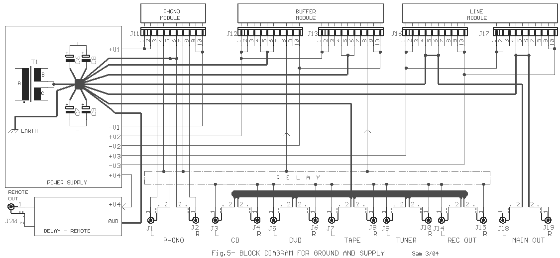
voltage supplies all the sel. Circuits, RL, delay and Remote. The earth line [0VD] of this
stage SHOULD be separate from the earth that concerns audio circuits [0VA] and will be
supposed it leads to the common point that leads all the earth sectors, between to
capacitors C6,7,8,9 [Fig.5]. Different and accidental
arrangement of earth lines will create hum problems. Certain stabilizers should be placed
on small heatsinks or in one common
bigger it�s enough it's placed between this and the stabilizers suitable silicon mica. |
| Delay Circuit |
| An essential circuit is the delay of connection of exit of
preamplifier in the inputs of power amplifiers, afterwards the passage of few times. This
protects are heard annoying sounds from the capacitors charge and recharge the moment
where we open and close the preamplifier. The circuit can be replaced from a transistor,
but I believe that solution with the use of IC9 ensures better and steadier behavior. All
the circuit is built round the IC9 and functions as follows. When closes switch S4 the
voltage in T1 secondary is rectified by D32,34 and via the R32 and D35 is stabilized in
+12V. The exit of IC9A becomes High and via the R33 charge the C36 the capacity of that
determines also the time of delay, in our case roughly 5 seconds [In order to grows this
time should grows also C36]. Hardly charge capacitor C36 the exit of IC9B becomes High and
transistor Q1 becomes ON, D37 turns on, is activated the relay RL12, the two contacts in
the exit of preamplifier [Fig.1] closes. On the contrary when switch S4 opens then the
voltage in secondary of T1 fall cutting off the same become also in the pins of 1,2 IC9A
so that are cut-off the circuit and the relay RL12 open, the himself and his contacts,
stopping the flow of acoustic signal to the power amplifiers. |
| Remote |
| The circuit Remote follows the operation of
previous circuit. When capacitor C36 is charge then the exit of IC9C becomes High the
transistor Q2 becomes on, diode D39 turns on also the relay RL13 closes his contacts,
allowing the AC voltage from the JF1 to pass in the JF2. Simultaneously the supply voltage
+12V is presented in exit J20, with which we have the possibility of driving one suitable
external relay. In this case if we did not need the relay RL13, we can suppress. The
usefulness of this circuit is obvious in the case where the preamplifier drives active
speakers, but does not exclude also other uses as the supply via plug JF2 with voltage
benefit in the remainder appliances that have relation with the preamplifier and need they
open with this, as power amplifiers, Cd player, Tuner etc. The contacts of RL13 IT SHOULD
THEY ENDURE the POWER THAT NEEDS the APPLIANCES THAT ARE SUPPLIED BY THEM. Where it exists
the 230Vac voltage should insulate very well. It will be supposed I stress that the
CONTACT WITH THESE POINTS, NEEDS the PROPORTIONAL ATTENTION, BECAUSE the HIGH VOLTAGE IS DANGEROUS. |
|
Part
List for Power supply-Delay time and Remote Unit [Fig.2] |
|
| R28-29-30-31=220ohm 1/4W metal film
1% |
C24-26-28-30-32-33=100nF 63V MKT 5% |
D35=12V 1W Zener |
| R32=1Kohm 1W 5% |
C25-29-27-31-34=10uF 25V |
D37-39=LED 3mm |
| R33=1Mohm 1/4W metal film 1% |
C35=100uF 63V |
Q1-2=BD678 |
| R34=10Kohm 1/4W metal film 1% |
C36=4.7uF 25V |
T1=230Vac//2X15V 50VA Transformer
[Toroidal] |
| R35-38=39Kohm 1/4W metal film 1% |
C37=47nF 63V MKT 5% |
RL13=12V Relay 2X2 20A [Finder -Omron] |
| R36-37-39=1Kohm 1/4W metal film 1% |
IC2=LM7815 or LM7818 |
F1=1A Slow Block Fuse |
| R40=1.2ohm 1/4W 5% |
IC3=LM7915 or LM7918 |
S4=2X2 Switch 10A per contact |
| TR1-2-3-4=4.7Kohm trimmer |
IC4-6=LM317 [above in small
Heatsink] [See text] |
JF1=3pin male supply jack with EMI Filter |
| C5=22nF 300Vac [Y2/X1 Class] MKT
20% |
IC5-7=LM337 [above in small
Heatsink] |
JF2=3pin female supply jack |
| C6-7-8-9=10000uF 35V |
IC8=LM7812 [above in small
Heatsink] |
J20=RCA Type Female gold-plated connectror [isolating] |
| C10-11-12-13=100nF 63V MKT 5% |
IC9=4081 [AND C-mos] |
|
| C14-15-17-19-21-23=10uF 25V |
B1=Bringe Rectifier [B80 C5000-3000] |
For ICs Techical Data see my
Database |
| C16-18-20-22=100nF 63V MKT 5% |
D23.....34-36-38=1N4002 |
All the MKT capacitors is polyester |
|
| . |
| Modular Preamplifier Technical Data Typical |
|
Input Selections |
5 stereo
sources |
|
|
Input Impedance |
47K ohms |
|
|
Audio Outputs |
1X Stereo Rec, 1X
stereo Main |
|
|
Main Output
Impedance |
100 ohms |
|
|
Recording Output
Impedance |
100 ohms |
|
|
Output Voltage |
1.2 VRMS |
|
|
Frequency
Response |
DC to 100KHZ
+-0.10 dB typ. |
|
|
Distortion |
Less than .01%
THD and IM typ. |
|
|
Crosstalk |
Greater than 90
dB typ. |
|
|
Noise |
105 dB A Weighted
@ 1 KHz typ. |
|
|
Mute Switch
Attenuation |
0, -20 dB
attenuation |
|
|
Delay time out
Protection |
~5 sec |
|
|
Remote outputs |
+12V [Protected],
AC Line |
|
|
Delay time Remote
output |
~5 sec |
|
|
AC Line Voltage |
120/230 volts
60/50 HZ |
|
|
AC Voltage Range |
+-10% |
|
|
|
|
|
|
|
Alternative
proposal for Buffer and Gain module Units |
|
|
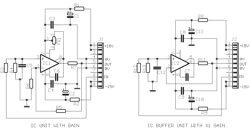
Fig.3
Fig.4 |
| In pictures fig.3-4 appear the alternative
proposals for those who they will prefer the opamp choice, from the solution of separately
components, in the place of each module. In the Fig.3 exists a typical circuit. In the
place of IC1 can use a line from choices of single opamp. The choices that I propose exist
in the part list. Certain opamp have pins in which we can place one small trimmer [TR1]
with which we have the possibility of regulating DC voltage [Offset voltage] in the exit
of IC. If without TR1, this voltage is low, we can omit this. Between pins 5 and 8 of IC1
we can place a capacitor with typical value 22pF, which decreases the open bronchus
bandwidth of IC with result better stability. The use the C6-8 is imposed when the
amplifier works with X1 gain. If the opamp gain don't suffices you can change the value of
resistor R5 following the type of gain calculation [A=R5+R6/R6]. Capacitors C3,4,8,9
should be placed near in ICs pins. Resistances R1,5,8,9 in combination with capacitors
C1,2,10,11 create a local filter for the supply stability. Resistors R7,11 protect the
opamp exits from short-circuit. In the Buffer unit the IC2 does not present no gain in the
signal. Good it�s in the place of IC2 is preferred opamp with FET in his input, because
this solution presents more tolerance in the changes of resistance in his input. In the
course of acoustic signal, in the exits and in the inputs of units don�t exist
capacitors. Thus the units have in the low frequencies, flat response. |
Part
List for Buffer and Gain Units [Fig.3-4] |
|
| R1-2-8-9=47ohm 1/4W 1% metal film |
C1-2-10-11=47uF 25V |
IC2=NE5534
- TL071 - OP07C-LF411-OPA604 |
| R3-6-12=1Kohm 1/4W 1% metal film |
C3-4-8-9=100nF 63V MKT |
J1-2=10pin pointed male connector 2.54mm step |
| R4-13=47Kohm 1/4W 1% metal film |
C5=1.5nF 100V MKT or stypoflex |
|
| R5=6.8Kohm 1/4W 1% metal film |
C6-7=22pF 100V ceramic or stypoflex |
All the MKT capacitors is polyester 5% |
| R7-11=100hm 1/4W 1% metal film |
IC1=NE5534-OPA604 |
For ICs Techical Data see my
Database |
|
| . |
Ground
and Supply Lines Block Diagram [Fig.5] |
|
| . |
In
photographs appears the prototype, in which base the circuits that exist here. They little
differ in the supply philosophy, the quantity of inputs-outputs and in the existence of
headphone amplifier that does not offer something in the sound quality. |
Sam
Electronic Circuits 03/04 |
|
|


